

Электросхема погрузчика John Deere 4WD Engine 6068HDW74
- SE1—Battery and Starter Circuits (24 Volt System)
- SE2—Alternator and Air Heater Circuits
- SE3—Ignition and Start Circuits
- SE4—Vehicle Electrical Center (VEC) Circuit (Fuses F01—F08 and Diode V2)
- SE5—Vehicle Electrical Center (VEC) Circuit (Fuses F08—F16)
- SE6—Vehicle Electrical Center (VEC) Circuit (Fuses F17—F29)
- SE7—Vehicle Electrical Center (VEC) Circuit (Fuses F31—F38 and Diode V3)
- SE8—Vehicle Electrical Center (VEC) Circuit (Fuses F40, F41, F49, and Diode V4)
- SE9—Vehicle Electrical Center (VEC) Circuit (Fuses F46 and F51—F56)
- SE10—Ride Control Circuit
- SE11—Counter Switch and Heated Side Mirrors (Optional) Circuits
- SE12—CAN 2 and Ground Speed Radar (Optional) Circuits
- SE13—CAN 2 and Embedded Payload Scale (Optional) Circuits
- SE14—CAN 1 and Service ADVISOR ™ Diagnostic Connector Circuits
- SE15—CAN 1 and Advance Display Unit (ADU) Circuits
- SE16—Fuel Level, Hydraulic Oil Filter Restriction, Boom Cylinder Pressure, and Steering Pressure Circuits
- SE17—BHKO/RTC, RTD, and Hydraulic Oil Temperature Circuits
- SE18—Flex Load Controller (FLC) and Service Brake Pressure Sensors Circuits
- SE19—Flex Load Controller (FLC), Proportional Fan Solenoid, and Monitor Alarm Circuits
- SE20—Reversing Fan and Horn Circuits
- SE21—Pilot Enable/Boom Down Solenoids and Secondary Steering Pump Motor Circuits
- SE22—Steering Column FNR/Gear Select Switch Circuit
- SE23—Backup Alarm and Transmission Speed Sensors Circuits
- SE24—Transmission Control Unit (TCU), Control Valve Solenoids, and Joystick (Loader) Control Switches Circuits
- SE25—Transmission Sensors and Switches Circuits
- SE26—Radar Object Detection (ROD) and Rear Camera Circuits (Optional)
- SE27—Hydraulic Control Lever Detents and Return-to-Dig Switch (Z-Bar) Circuits
- SE28—Differential Lock and Pin Disconnect Circuits
- SE29—Air Seat Adjust and Seat Heater Circuits
- SE30—Front and Rear Wiper/Washer Circuits
- SE31—Heater and Precleaner Blower Circuits
- SE32—Air Conditioning Circuit
- SE33—Turn Light Circuits
- SE34—Marker Lights, Tail Lights, and License Plate Light Circuits
- SE35—Drive Lights and Rotary Beacon Circuits
- SE36—Brake Lights and and Dome Light Circuits
- SE37—Front and Rear Cab Work Lights and Front Auxiliary Lights Circuits
- SE38—24V/12V Converter and Radio Circuits
- SE39—Sealed Switch Module (SSM) Circuit
- SE40—Not Used
- SE41—Engine Sensors (B6, B23, B47, B48, and B51) Circuits
- SE42—Engine Control Unit (ECU) and Sensors (B3, B4, B14, and B49) Circuits
- SE43—Engine Control Unit (ECU) and Sensors (B55, B56, and B57) Circuits
- SE44—Engine Air Filter Restriction Switch and High Pressure Fuel Pump Solenoid Circuits
- SE45—Engine Electronic Injectors (Y21—Y26) Circuits
- SE46 — JDLink ™ Machine Information Connectors and Ground Return Fuse (F66) Circuit (Optional)
- SE47 —JDLink™ GlobalTRACS ® Terminal (GTT) Circuit (Optional)
- SE48 —JDLink™ Machine Information Gateway (MIG) Circuit (Optional) (S.N. —634735)
- SE49 —JDLink™ Satellite (SAT) (Optional) and Modular Telematics Gateway (MTG) Circuit (S.N. 634736— )
System Functional Schematic (SE1—SE3)

- E26 - Air Heater (if equipped)
- F65 - Air Heater 125-Amp Fuse (inline)
- G1 - Batteries
- G2 - Emergency Starting Terminal
- G4 - Alternator
- K3 - Start Relay
- K4 - Ignition Relay
- K5 - Air Heater Relay
- M1 - Starter Motor
- S2 - Battery Disconnect Switch
- V1 - Starter Coil Suppression 5-Amp Diode
- V6 - Air Heater Relay Suppression Diode
- W25 - Ground at Starter Motor (for circuits G01, G03, G11, G20, G21, and G22 BLK)
- W26 - Ground at Right Front Cab Leg (for circuits G04, G05, and G08 BLK)
- W27 - Ground at Engine Frame (near starter) (for circuit G02 BLK)
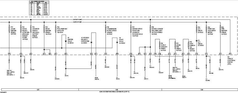
System Functional Schematic (SE4—SE6)

- F01 - JDLink ™ Battery Power 10-Amp Fuse
- F02 - Sealed Switch Module (SSM) Battery Power 5-Amp Fuse
- F03 - Engine Control Unit (ECU) Battery Power 20-Amp Fuse
- F04 - 24V/12V Converter, Rear Camera, and Radio Battery Power 15-Amp Fuse
- F05 - Blower Motors 25-Amp Fuse
- F08 - Air Seat Adjust and Heat 20-Amp Fuse
- F09 - 24V/12V Converter and Radio Ignition Power 10-Amp Fuse
- F10 - Engine Control Unit (ECU) Ignition Power 5-Amp Fuse
- F11 - RTD and Quick Shift Switches 10-Amp Fuse
- F13 - ADU, Monitor Alarm, Turn Signal, and Counter Switch Ignition Power 5-Amp Fuse
- F15 - Spare Ignition Power 5-Amp Fuse
- F16 - Spare Ignition Power 15-Amp Fuse
- F17 - Spare Battery Power 15-Amp Fuse
- F18 - Transmission Control Unit (TCU) Battery Power 5-Amp Fuse
- F20 - Engine Compartment Light Battery Power 10-Amp Fuse (not used)
- F21 - Flex Load Controller (FLC) Battery Power 10-Amp Fuse
- F23 - Differential Lock, Steering Pressure, and Park Brake Switch 5-Amp Fuse
- F28 - Transmission Control Unit (TCU) Ignition Power 5-Amp Fuse
- F29 - Joystick Steering Ignition Power 5-Amp Fuse (not used)
- G8 - Vehicle Electrical Center (VEC)
- V2 - Spare 3-Amp Diode (marked as Start Aid Solenoid Coil) (located on VEC)
- W26 - Ground at Right Front Cab Leg (for circuits G04, G05, and G08 BLK)
- X10 - Vehicle Electrical Center 8-Pin GRY Connector
- X11 - Vehicle Electrical Center 8-Pin RED Connector
- X12 - Vehicle Electrical Center 8-Pin BLK Connector
- X13 - Vehicle Electrical Center 8-Pin ORG Connector
- X14 - Vehicle Electrical Center 2-Pin GRY Connector
- X15 - Vehicle Electrical Center 2-Pin BLK Connector
- X16 - Vehicle Electrical Center 8-Pin BLU Connector
- X17 - Vehicle Electrical Center 8-Pin GRN Connector
- X18 - Vehicle Electrical Center 8-Pin BRN Connector
- X19 - Load Center Harness Spare Battery Power (F17) Connector
- X20 - Load Center Harness Spare Ignition Power (F16) Connector
- X21 - Load Center Harness Spare Ground Connector
- X31 - Load Center Harness-to-Joystick Steering Harness 23-Pin Connector (not used)
- X114 - Engine Compartment Light Switch 2-Pin Connector (not used)
System Functional Schematic (SE7—SE9)
- F31 - JDLink ™ Ignition Power 5-Amp Fuse
- F32 - Radar Object Detection (ROD) and Backup Alarm 5-Amp Fuse
- F33 - Advanced Display Unit (ADU) Battery Power 5-Amp Fuse
- F34 - Spare Ignition Power 10-Amp Fuse
- F38 - Fuel Pump and Air Filter Restriction 15-Amp Fuse
- F40 - Transmission Output Speed Sensor 5-Amp Fuse
- F41 - Ground Speed Radar and Advanced Payload Scale Ignition Power 10-Amp Fuse
- F46 - 12-Volt Auxiliary Power Connector 5-Amp Fuse
- F49 - Service ADVISOR ™ and Dome Light Battery Power 5-Amp Fuse
- F51 - JDLink™ Run Signal 5-Amp Fuse
- F52 - Rear Camera 12-Volt Power 5-Amp Fuse
- F53 - Alternator Excitation Ignition Power 5-Amp Fuse
- F55 - Front and Rear Wiper Motor 5-Amp Fuse
- F56 - Tire Pressure Monitoring (TPM) System Ignition Power 5-Amp Fuse (if equipped)
- G8 - Vehicle Electrical Center (VEC)
- V3 - Ignition Relay 3-Amp Diode (located on VEC)
- V4 - Start Relay 3-Amp Diode (located on VEC)
- V5 - Alternator Excitation 3-Amp Diode (located on VEC)
- V7 - Reverse Polarity Protection 3-Amp Diode (located on VEC)
- X10 - Vehicle Electrical Center 8-Pin GRY Connector
- X11 - Vehicle Electrical Center 8-Pin RED Connector
- X12 - Vehicle Electrical Center 8-Pin BLK Connector
- X13 - Vehicle Electrical Center 8-Pin ORG Connector
- X14 - Vehicle Electrical Center 2-Pin GRY Connector
- X15 - Vehicle Electrical Center 2-Pin BLK Connector
- X16 - Vehicle Electrical Center 8-Pin BLU Connector
- X17 - Vehicle Electrical Center 8-Pin GRN Connector
- X18 - Vehicle Electrical Center 8-Pin BRN Connector
System Functional Schematic (SE10—SE12)

- A13 - Tire Pressure Monitoring (TPM) Unit (if equipped)
- A14 - Ground Speed Radar Sensor (RDR) Unit
- B41 - Ride Control Pressure Switch (closes with pressure)
- E13 - Left Heated Mirror
- E14 - Right Heated Mirror
- R5 - CAN 2 Termination Resistor
- S18 - Cycle Counter Switch
- W25 - Ground at Starter Motor (for circuits G01, G03, G11, G20, G21, and G22 BLK)
- W26 - Ground at Right Front Cab Leg (for circuits G04, G05, and G08 BLK)
- X100 - Ground Speed Radar Connector
- X104 - Tire Pressure Monitoring (TPM) System Connector
- Y17 - Ride Control Boom Solenoid
- Y18 - Ride Control (On/Off) Solenoid 1
- Y34 - Ride Control (On/Off) Solenoid 2
System Functional Schematic (SE13—SE15)

- A15 - Advanced Payload Scale Unit
- H2 - Advanced Display Unit (ADU)
- R1 - CAN 1 Termination Resistor
- R2 - CAN 1 Termination Resistor
- R4 - CAN 2 Termination Resistor
- W25 - Ground at Starter Motor (for circuits G01, G03, G11, G20, G21, and G22 BLK)
- W26 - Ground at Right Front Cab Leg (for circuits G04, G05, and G08 BLK)
- X1 - Service ADVISOR ™ Diagnostic Connector
- X31 - Load Center Harness-to-Joystick Steering Harness 23-Pin Connector (not used)
- X48 - Advanced Display Unit (ADU) 12-Pin Connector
- X60 - 4-Pin Connector (not used)
- X103 - Advanced Payload Scale Connector (if equipped)
System Functional Schematic (SE16—SE18)
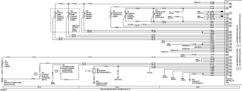
- A2 - Flex Load Controller (FLC)
- B8 - Hydraulic System Pressure Sensor
- B15 - Hydraulic Oil Temperature Sensor
- B17 - Fuel Level Sensor
- B21 - Hydraulic Oil Filter Restriction Switch
- B25 - Steering System Pressure Switch (closes with high pressure)
- B27 - Service Brake Pressure Sensor (front axle) (closes with high pressure)
- B45 - Analog BHKO/RTC Position Sensor
- B63 - Rod-End Boom Cylinder Pressure Sensor
- B64 - Head-End Boom Cylinder Pressure Sensor
- S23 - Horn Switch (on steering wheel)
- W25 - Ground at Starter Motor (for circuits G01, G03, G11, G20, G21, and G22 BLK)
- W26 - Ground at Right Front Cab Leg (for circuits G04, G05, and G08 BLK)
- W27 - Ground at Engine Frame (near starter) (for circuit G02 BLK)
- X31 - Load Center Harness-to-Joystick Steering Harness 23-Pin Connector (not used)
- X40 - Flex Load Controller (FLC) Connector (J1) (BRN)
- X41 - Flex Load Controller (FLC) Connector (J2) (BRN)
- X42 - Flex Load Controller (FLC) Connector (J3) (BLU)
- X43 - Flex Load Controller (FLC) Switch Power Connector (J4) (back of controller)
System Functional Schematic (SE19—SE21)

- A2 - Flex Load Controller (FLC)
- B38 - Horn
- H1 - Monitor Alarm
- M8 - Secondary Steering Pump Motor
- W25 - Ground at Starter Motor (for circuits G01, G03, G11, G20, G21, and G22 BLK)
- W26 - Ground at Right Front Cab Leg (for circuits G04, G05, and G08 BLK)
- W27 - Ground at Engine Frame (near starter) (for circuit G02 BLK)
- X40 - Flex Load Controller (FLC) Connector (J1) (BRN)
- X41 - Flex Load Controller (FLC) Connector (J2) (BRN)
- X42 - Flex Load Controller (FLC) Connector (J3) (BLU)
- X43 - Flex Load Controller (FLC) Switch Power Connector (J4)
- X61 - Pilot Controller Detent Coils Connector (not used)
- Y14 - Pilot Enable Solenoid
- Y15 - Boom Down Accumulator Solenoid
- Y37 - Proportional Fan Solenoid
- Y38 - Reversing Fan Solenoid
System Functional Schematic (SE22—SE24)

- A3 - Transmission Control Unit (TCU)
- B28 - Torque Converter Input Speed Sensor (engine speed)
- B29 - Torque Converter Output Speed Sensor
- B30 - Internal Clutch Speed Sensor
- B31 - Transmission Output Shaft Speed Sensor
- H3 - Backup Alarm
- S7 - Quick Shift Switch
- S9 - Joystick (Loader) Forward, Neutral, Reverse (FNR) Switch
- S10 - Steering Column FNR/Gear Select Switch
- S11 - Joystick (Loader) Gear Downshift Switch
- S12 - Joystick (Loader) Gear Upshift Switch
- X23 - TCU Connector
- X27 - Joystick Loader FNR Switch and Gear Select Switches Connector
- X50 - Steering Column FNR Portion of Switch (S10) 4-Pin Connector
- X51 - Steering Column Gear Select Portion of Switch (S10) 4-Pin Connector
- Y1 - Transmission Control Solenoid 1
- Y2 - Transmission Control Solenoid 2
- Y3 - Transmission Control Solenoid 3
- Y4 - Transmission Control Solenoid 4
- Y5 - Transmission Control Solenoid 5
- Y6 - Transmission Control Solenoid 6
- Y28 - Rear Axle Disconnect Solenoid
System Functional Schematic (SE25—SE27)
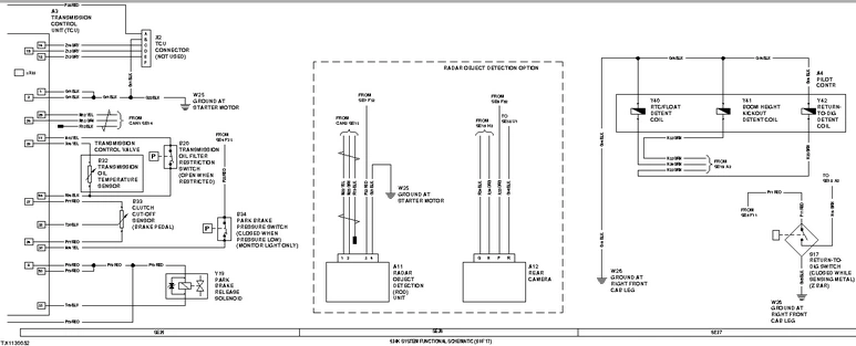
- A3 - Transmission Control Unit (TCU)
- A4 - Pilot Controller
- A11 - Radar Object Detection (ROD) Unit
- A12 - Rear Camera
- B20 - Transmission Oil Filter Restriction Switch
- B32 - Transmission Oil Temperature Sensor
- B33 - Clutch Cut-Off Sensor (brake pedal)
- B34 - Park Brake Pressure Switch (closes with low pressure)
- S17 - Return-to-Dig Switch (Z-Bar) (closes when sensing metal)
- W25 - Ground at Starter Motor (for circuits G01, G03, G11, G20, G21, and G22 BLK)
- W26 - Ground at Right Front Cab Leg (for circuits G04, G05, and G08 BLK)
- X2 - TCU Diagnostic and Programming Connector (not used)
- X23 - TCU Connector
- Y19 - Park Brake Release Solenoid
- Y40 - RTC/Float Detent Coil
- Y41 - Boom Height Kickout Detent Coil
- Y42 - Return-To-Dig Detent Coil
System Functional Schematic (SE28—SE30)
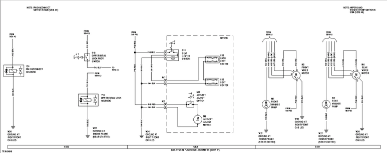
- E32 - Seat Heater
- E33 - Seat Back Rest Heater
- M2 - Front Washer Pump
- M3 - Front Wiper Motor
- M4 - Rear Washer Pump
- M5 - Rear Wiper Motor
- M9 - Air Seat Adjust Motor
- S13 - Differential Lock Foot Switch
- S32 - Air Seat Adjust Switch
- S33 - Seat Heater Switch
- W26 - Ground at Right Front Cab Leg (for circuits G04, G05, and G08 BLK)
- W27 - Ground at Engine Frame (near starter) (for circuit G02 BLK)
- X33 - Load Center Harness-to-Air Adjust Seat Harness 2-Pin Connector
- X47 - Heated Seat 2-Pin Connector
- Y13 - Differential Lock Solenoid
- Y20 - Pin Disconnect Solenoid
System Functional Schematic (SE31-SE33)

- B35 - Freeze Control Switch
- B50 - Air Conditioner Binary Pressure Switch (opens with high pressure and low pressure)
- E2 - Left Front Turn Light
- E3 - Left Rear Turn Light
- E4 - Right Front Turn Light
- E5 - Right Rear Turn Light
- M6 - Blower Motor
- M7 - Precleaner Blower Motor
- R3 - Blower Speed Resistor
- S21 - Blower Speed Switch
- S25 - Turn Switch
- V11 - Air Conditioner Compressor Clutch 1-Amp Diode
- W25 - Ground at Starter Motor (for circuits G01, G03, G11, G20, G21, and G22 BLK)
- W26 - Ground at Right Front Cab Leg (for circuits G04, G05, and G08 BLK)
- W27 - Ground at Engine Frame (near starter) (for circuit G02 BLK)
- Y16 - Air Conditioner Compressor Clutch
System Functional Schematic (SE34—SE36)

- E6 - Left Front Marker Light
- E7 - Right Front Marker Light
- E8 - Left Tail Light
- E9 - Right Tail Light
- E10 - License Plate Light
- E11 - Left Front Drive Light
- E12 - Right Front Drive Light
- E15 - Rotary Beacon Light
- E16 - Left Rear Brake Light
- E17 - Right Rear Brake Light
- E18 - Dome Light
- S28 - Dome Light Switch
- S29 - Door Switch (opens when door closed)
- W26 - Ground at Right Front Cab Leg (for circuits G04, G05, and G08 BLK)
- W27 - Ground at Engine Frame (near starter) (for circuit G02 BLK)
System Functional Schematic (SE37—SE39)
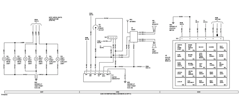
- A5 - Radio
- A6 - Sealed Switch Module (SSM)
- B42 - Left Speaker
- B43 - Right Speaker
- E20 - Left Front Work Light
- E21 - Right Front Work Light
- E22 - Left Rear Work Light
- E23 - Right Rear Work Light
- E24 - Left Front Auxiliary Light
- E25 - Right Front Auxiliary Light
- G5 - 12-Volt Power Outlet
- S35 - Ignition ON/Engine START Switch (located on SSM)
- S36 - Engine STOP/Ignition OFF Switch (located on SSM)
- S37 - Beacon Light Switch (located on SSM)
- S38 - Hazards Light Switch (located on SSM)
- S39 - Pilot Enable/Boom Down Switch (located on SSM)
- S40 - Park Brake Switch (located on SSM)
- S41 - Return-to-Dig Enable Switch (located on SSM)
- S42 - Automatic Transmission Switch (located on SSM)
- S43 - Ride Control Switch (located on SSM)
- S44 - Clutch Cut-Off Enable Switch (located on SSM)
- S45 - Boom Height Kickout Enable Switch (located on SSM)
- S46 - Return-to-Carry Enable Switch (located on SSM)
- S47 - Auto-Differential Lock Enable Switch (located on SSM)
- S48 - Spin Control Enable Switch (located on SSM)
- S49 - Pin Disconnect Switch (located on SSM)
- S50 - Air Conditioning (On/Off) Switch (located on SSM)
- S51 - Heated Side Mirrors Switch (located on SSM)
- S52 - Front Washer Switch (located on SSM)
- S53 - Front Wiper Switch (located on SSM)
- S54 - Drive Lights Switch (located on SSM)
- S55 - Torque Converter Lock Up Enable Switch (located on SSM)
- S56 - Auto-Axle Disconnect Switch (located on SSM)
- S57 - Rear Washer Switch (located on SSM)
- S58 - Rear Wiper Switch (located on SSM)
- S59 - Work Lights Switch (located on SSM)
- U1 - 24V/12V Converter
- W24 - Antenna
- W25 - Ground at Starter Motor (for circuits G01, G03, G11, G20, G21, and G22 BLK)
- W26 - Ground at Right Front Cab Leg (for circuits G04, G05, and G08 BLK)
- X53 - Sealed Switch Module (SSM) 6-Pin Connector
- X91 - Spare 12-Volt 4-Pin Connector
System Functional Schematic (SE40—SE42)

- A1 - Engine Control Unit (ECU)
- B1 - Engine Coolant Temperature Sensor
- B3 - Camshaft Position Sensor
- B4 - Crankshaft Position Sensor
- B5 - Fuel Temperature Sensor
- B7 - Manifold Air Temperature (MAT) Sensor
- B14 - Analog Throttle Position Sensor
- B23 - Engine Oil Pressure Sensor
- B48 - Water in Fuel (WIF) Sensor
- B49 - Fuel Rail Pressure Sensor
- X71 - Engine Control Unit (ECU) Connector (J1) (BLK)
- X72 - Engine Control Unit (ECU) Connector (J2) (BRN)
System Functional Schematic (SE43—SE45)

- A1 - Engine Control Unit (ECU)
- B10 - Ambient Air Temperature Sensor
- B19 - Engine Air Filter Restriction Switch (closed with restriction)
- W25 - Ground at Starter Motor (for circuits G01, G03, G11, G20, G21, and G22 BLK)
- W27 - Ground at Engine Frame (near starter) (for circuit G02 BLK)
- X49 - Engine Harness-to-Electronic Injector (EI) Harness 12-Pin Connector
- X71 - Engine Control Unit (ECU) Connector (J1) (BLK)
- X72 - Engine Control Unit (ECU) Connector (J2) (BRN)
- Y7 - Start Aid Solenoid
- Y8 - High Pressure Fuel Pump Solenoid
- Y21 - Electronic Injector (Cylinder #1)
- Y22 - Electronic Injector (Cylinder #2)
- Y23 - Electronic Injector (Cylinder #3)
- Y24 - Electronic Injector (Cylinder #4)
- Y25 - Electronic Injector (Cylinder #5)
- Y26 - Electronic Injector (Cylinder #6)