

Engine control with MR-PLD
(тренинг персонала)

Safety
- Symbols
- General information
- Use for the indended purpose
- Personnel requirements
- Conversions and modifications to the MR-PLD
- Installation
- Organizational measures
- Safety precautions for engines with electronic control units
- DaimlerChrysler original parts
- Safety and backup running programm
- General governor architecture
- Standard model of engine control (MR-PLD) and vehicle electronics (FRE)
- Features of the governor and interface module
- VCU (ADM2) as FRE (vehicle electronics)
- ADM as FRE (vehicle electronics)
MR-PLD engine control (pump-line-nozzle)
- Brief description of the Diesel engine control unit PLD-MR
- Control unit - operating principle
- Overview of the telligent engine system BR 500
- Overview of the telligent engine system BR 900
- Control unit block diagram
- PLD control unit as engine control (MR-PLD)
- Functional description
- Configuration
- Flexibility of the concept
- Control unit description of engine electronics MR-PLD
- Safeguard /redundancy
- Description of the inputs
- Description of the outputs
- Compound network between MR-PLD <=> FRE
- Communication
- MR-PLD <=> FRE interface functions
- Idle-speed control / speed control / maximum engine speed limitation
- Shutoff or throttling of the engine through the FRE (vehicle electronics)
- Engine start and stop
- Starter control (conditions)
- Starter protection
- Start by the driver
- CAN start
- Starter reset bridge
- Starter driver
- Start through the FRE (vehicle control electronics) via CAN
- Starting procedure
- Service start button at the engine block
- Service stop button at the engine block
- Engine cranking via the service start and stop button
- Rev up to maximum speed via service start button
- Engine stop
- Plausibility check terminal 50
- Calculation of injection delivery angle and start of injection
- Controls (PID governor)
- Operating modes
- PTO speed control
- Controlled operation (normal operation)
- Immobilizer
- Tow starting of the engine
- Emergency syndrome
- Mechanical description
- Mechanical layout of PLD engine electronics
- Complete version PLD engine electronics
- Fuel cooling
- MR-PLD Control Unit
- MR-PLD - version assignment table
- Technical data
- General testing conditions
Electrical description
- System interface diagram
- Interface diagram
- Socket pin designation MR-PLD control unit (D2.1)/according to pin assignment
- Pin assignment of MR-PLD control unit (D2.1); function oriented/alphabetical
- Voltage supply of control unit MR-PLD (D2.1)
- Sensor system of the PLD engine control unit (MR-PLD)
- Control unit internal sensors
- Control unit external sensors
- Active sensors
- Passive sensors
- Temperature sensors
- Passive oil pressure
- Oil level
- Camshaft / crankshaft position (inductive)
- Booster speed 1 / 2
- Fan speed
- Digital inputs
- Ignition (Terminal 15)
- Terminal 50
- Service button start/stop
- Oil separator
- Proportional valve control
- Functional assignment of proportional valves/hardware status D2.1
- Principle block diagram proportional valve control /hardware status D2.1
- Functional assignment of the proportional valves/hardware status C3..C6
- Principle block diagram proportional valve control/hardware status C3..C6
- Starter control through the MR-PLD
- Main path (self-locking)
- Auxiliary path (self conducting)
- Principle block diagram starter control
- Starter relay
- Principle block diagram of safety concept of JE-starter
- Serial communication interfaces
- CAN data bus (2-wire-interface, standard: ISO 11992)
- Diagnostic line (standard: ISO 9141)
- Classification of the injector valves
Configuration possibilities of the MR-PLD
- Fan type
- General connection
- Pin assignment of the proportional valve-power stages (PV/Prop) for fan control
- Type 0/Linning-clutch (on highway/two-stage)
- Type 1/Linning-clutch (off highway/two-stage)
- Configuration / fan switch-on threshold (type 1)
- Type 2 /electrically controlled Viscous-fan
- Type 3 /Hydrostatic Fan
- Type 4/Horton-clutch
- Type 5/one Hydrostatic-fan
- Type 6/two Hydrostatic-fans
- Starter control
- JE-starter
- KB-starter
- KB-starter with starter solenoid relay (2 A)
- KB-starter without Starter Solenoid Relay (2 A)
- Oil pans
Diagnosis
- Measured values
- Analogue measured values
- Binary measured values
- Serial diagnosis interfaces
- Diagnostic line
- Fault memory
- Operating modes
- CAN data bus systems
- Engine-CAN (ISO 11992)
- Vehicle CAN
- SAE J1587/SAE J1708 (USA- and partly NAFTA-market)
- Configuration of diagnostic interface
- MB-truck / Brazil
- Europe (ADM / not MB-trucks)
- Europe (ADM2 / not MB-Trucks)
- USA- and partly NAFTA-market
- Diagnosis interface/software description
- Fault memory structure
- Ground switching
- Diagnosis unit & application
- Display/delete fault code memory
- Testing routines
- Voltmeter function
- Cylinder cutoff
- Compression check
- Idle speed balance (hot engine!)
- Impact delay time
- Calibration
- Single parameters
- Data set calibration
- Save modified parameter set
- Convert modified parameter set
- Program protection
- Stardiagnose
- ServiceLink
- Diagnosis routines
- Detailed testing routines
Backup
- System backup capability
- Microprocessor 1-backup
- Crankshaft backup
- Camshaft backup
- CAN-backup (definition)
- CAN-backup, mode 0 (standard-backup)
- CAN-backup, mode 1
- CAN-backup, mode 2
- CAN data-area check
- Nominal engine speed CAN-backup
- Nominal engine speed CAN-backup mode 0
- Nominal engine speed CAN-backup mode 1
- Microprocessor 2-backup
- Backup functions
- Ambient pressure sensor
- Boost pressure control
- Sensor-replacement values
- Plausibility limits and sensor replacement values
- Diagnosis of sensor and backup functions
- Temperature and presure sensors
- Crankshaft sensor
- Camshaft sensor (cylinder 1 recognition)
- Diagnosis of actuators
- MR-PLD injector-/magnetic valves (MV)
- MR-PLD proportional valves
- Starter control
Fault codes & repair instructions
- Fault codes
- Fault priority 0
- Fault priority 1
- Fault priority 2
- Fault path
- Fault type
- Fault codes und repair instructions, high priority
- Fault codes und repair instructions, mean priority
- Fault codes und repair instructions, minor priority
Special measurements
- General information
- Actuators
- Solenoid valves: Current modulation curve of the injector valve control/type 1
- Solenoid valves: Current modulation curve of the injector valve control/ type 2
Parameters (minidiag2)
- MR-PLD Diagnosis version 3 to 5 (up-/download)
- MR-PLD Diagnosis from version 6 (single parameters)
Overview of the telligent engine system BR 500

A3 Controller FRE (FR-FMR)
A4 Controller Ignition System
A6 Controller MR-PLD
A42 Electronic to read Transponder Code
Bl Accelerator Pedal]
B2 Clutch Pedal
B3 Engine Speed Sensor at Counter Shaft
R4 Outside Temperature Sensor
B6 Engine Coolant Level Sensor
B7 Air Filter Inspection Sensor
B9 Turbo Charger Temperature Sensor
BIO Fuel Temperature Sensor
Bll Oil Temperature Sensor
B12 Oil Pressure Sensor
B13 Turbo Charger Pressure Sensor
B14 Oil Level Sensor
B15 Crankshaft Angle Position Sensor
B16 TDC Sensor Cylinder 1
R65 Coolant Temperature Sensor
G2 Alternator
M1 Starter
Pl Speedometer
51 Driving Switch
52 Lever for Engine Governor/ Permanent Rrake
53 Split Switch
54 Braking Light Switch
57 Switch for Reverse Gear
58 Switch for Group Position
59 Switch for Neutral Position
510 Push-button Engine Start
511 Push-button Engine Stop
Y1 Constant Throttle Magnetic Valve
Y2 Engine Rrake Magnetic Valve
Y29 MS2 Magnetic Valve
Y30 MSI Magnetic Valve
Overview of the telligent engine system BR 900

A3 Controller FRE (FR-FMR)
A4 Controller Ignition System
A6 Controller MR-PLD
A42 Electronic to read Transponder Code
Bl Accelerator Pedal
B2 Clutch Pedal
B3 Engine Speed Sensor at Counter Shaft
B4 Outside Temperature Sensor
B6 Engine Coolant Level Sensor
B7 Air Filter Inspection Sensor
B9 Intake Air Temperature Sensor
BIO Fuel Temperature Sensor
В14 Oil Level Sensor
B15 Crankshaft Angle Position Sensor
B16 TDC Sensor Cylinder 1
B65 Coolant Temperature Sensor
B110 Oil Pressure and Temperature Sensor
Bill Turbo Charger Air Pressure and Temperature Sensor
G2 Alternator
Ml Starter
Pl Speedometer
51 Driving Switch
52 Lever for Engine Governor/ Permanent Brake
S4 Braking Light Switch
S7 Switch for Reverse Gear
S9 Switch for Neutral Position
510 Push-button Engine Start
511 Push-button Engine Stop
S85 Switch 1, Clutch (KUP1) < 15 tons
S89 Switch 2, Clutch (KUP2) > 15 tons
Y1 Engine Brake Magnetic Valve (4 cyl.)
Exhaust Flap brake (6 cyl.)
Y2 Constant Throttle Magnetic Valve (6 cyl.)
Y6.. 11 Pump nozzle unit
Y63 Split Magnetic Valve
Y64 Shift Power Assistant Magnetic Valve G 100
Functional description
Configuration
The electronic system is divided in two independent subsystems that can be monitored separately.
The cabin mounted control unit “FRE” (vehicle electronics) controls the sensors and actuators attached to the drivers cab or the vehicle frame and involves all functions which are relevant for the vehicle.
The engine mounted control unit MR-PLD controls all sensors and actuators attached to the engine and involves all functions which are important to the engine operation.
The two control units are connected via a bus connection with “one wire capability”. Via this bus connection nominal values and the operating mode of the engine are demanded by the respective FRE (e.g. increase of idle speed, speed-controlled engine operation with programmable desired speed, torque limitation, freely selectable control characteristic, engine braking torque etc.), and in the opposite direction the MR-PLD control unit transmits information about the actual engine operating mode to the FRE (e.g. flame start unit).
Advantages:
– the plug connections at the engine are reduced to the connections which are relevant to the engine
– the vehicle connections are located in the uncritical surrounding area of the drivers cab (high degree of acceleration- and temperature load at the engine)
– less connection lines between engine and vehicle (reduced to the EMV-uncritical CAN connection) proves to be of particular advantage in the bus (due to the great distance between the control elements and the engine, like accelerator pedal etc.)
– the computers are only burdened with the functions and tasks of the particular system (the PLD-MR computer is only responsible for the engine management, no load through vehicle functions) – a modular extension of the system is possible by means of additional units that are connected with
the bus system
Flexibility of the concept
Each subsystem is tuned individually and can be tested as a subsystem. Therefore the engine can be replaced by an engine of a different design but with the same category of engine performance, without having to change the configuration in the vehicle-control unit (FRE) (e.g. PLD-MR engine is replaced by
Common-Rail engine). 4-, 5-, 6-, and 8-cylinder engines can be operated with the same PLD-MR.
Accessory parts at the engine like “Waste Gate”, fan high speed etc. can be regulated, controlled and connected via 6 PWM outputs at the PLD-MR. An additional digital output is reserved for the starter control! Functional requests of other electronic systems like ABS, ASR, EPB, EAS, automatic transmission, retarder etc. (data exchange via vehicle-CAN-Bus (e.g. IES-CAN)) are coordinated in the FRE and prepared for the engine electronics (PLD-MR).
Control unit description of engine electronics MR-PLD
The module MR-PLD engine electronics consists of the control unit and the fuel cooling. The MR-PLD control unit consists of a component circuit board with base plate (planar technique) and a zinc pressure die casting housing. The circuit board/base plate combination is screwed to the housing. The seal between
housing and circuit board is achieved by means of a fluid gasket.
The external electrical contact is maintained via a 16 pin and a 55-pin socket. To bring the pressure inside the housing into equilibrium with the ambient pressure, a pressure sensitive membrane is located on the bottom of the housing. The housing has 4 eyelets to accommodate the damping elements and screw them onto the engine. See also chapter 3.4. Mechanical description.
Compound network between MR-PLD <=> FRE
Communication
The FRE makes demands on the MR-PLD via the CAN like e.g.:
- Torque demand through accelerator pedal (controlled operation i.e. normal operation)
- ADR-governor type (5 types altogether, see following chapter 3.3.10.
- in the case of ADR mode: desired speed and max. torque
The MR-PLD sends the following data to the FRE:
- Actual value (sensor values) like speed, temperature, pressure.....
- Feedback of operating mode
Starter protection
For reasons of safety the starter is locked, switched off or disengaged if:
− In the case of a switched off ignition terminal 15, the engine can not be started by the actuation of terminal 50
− The starter control disengages the starter automatically, if the maximum engine speed for the starter operation (set by the factory) is exceeded, and therefore protects the starter from overspeed damage
− The maximum starting period is limited, therefore a starting interlock takes place if the authorized period is exceeded, in order to prevent a burning-out of the starter. After a wait period (for at least one second after the starter switch off) the starting procedure can be executed once again
− A starter lockout exists, as long as the engine speed is above 50 rpm. (cranking state “engine runs”)
− The engine runs and the starter is not engaged (cranking state “engine runs”)
− The starting interlock of CAN is active
− In the case of an automatic transmission an engine start is only possible, if the FRE input “neutral position” is activated
The starter is also locked if the engine control unit (MR-PLD) Parameter is set on KB-starter. In this case the text “starter-typ KB” is displayed in the starter status. A control of the starter is still not possible, if three short circuit events have been detected at the output of the starter driver. In this case the text “starter KS” is already displayed in the starter status when the first event takes place.
For reasons of security the signal which has caused a start has to be cancelled, before a renewed start due to the same signal is possible (interlock).
Starter driver
The starter driver has a multiple redundancy. The so-called main path consists of two transistors connected in series, which are powered by the battery voltage. In normal function the starter control takes place via this main path.
The so-called auxiliary path is powered via terminal 50 and can be released via terminal 50 in the case of a start, if e.g. the main path is defective. The auxiliary path is also used if the main controller of the engine control unit is defective. Due to the fact that the auxiliary path has no hardware short circuit protection, it is fundamentally used only after the activation of the main path, if furthermore there has been no signal detected via the main path.
The main controller can activate the main path (STA1 and STA2) and disable or release the auxiliary path (STA-NOT). A level measurement at the starter driver output (STA-level) and a short circuit detection (STAshort circuit detection) in the main path serve for the fault recognition.
Starter driver

Electrical description
System interface diagram
The 55 pin and the 16 pin sockets are the interfaces of the system. In the following block diagram the modules are combined in main groups. The exact pin assignment lists are on the following pages.
Interface diagram

Socket pin designation MR-PLD control unit (D2.1)/according to pin assignment
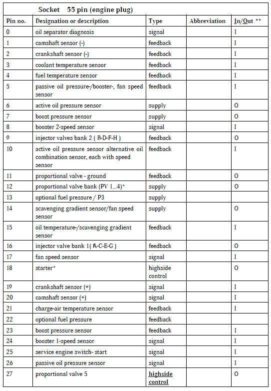
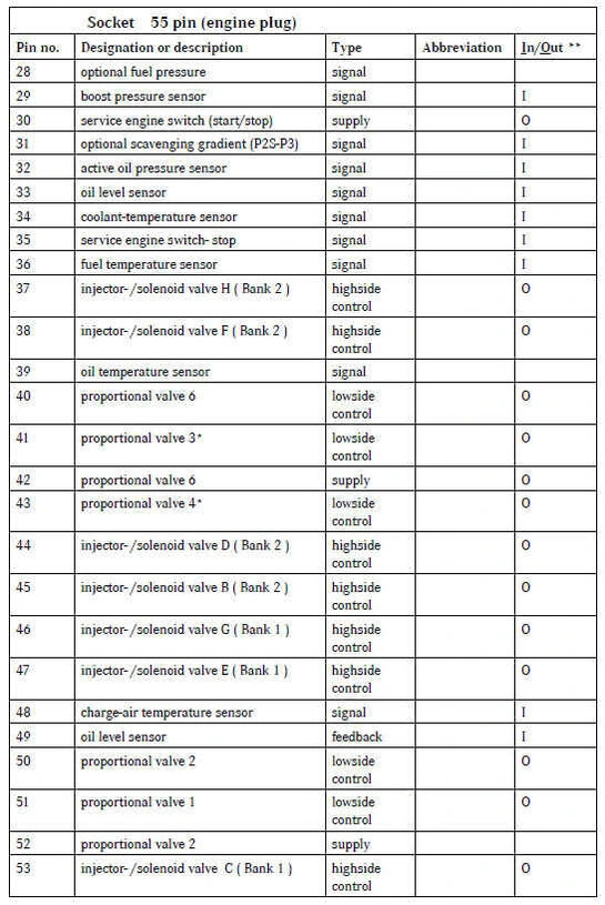

*: signal also on vehicle plug
** : In = input/Out = output

*: signal also on vehicle plug
** : In = input/Out = output
NC: not connected
Pin assignment of MR-PLD control unit (D2.1); function oriented/alphabetical


*: signal also on vehicle plug
** : In = input/Out = output

*: signal also on vehicle plug
** : In = input/Out = output
NC: not connected
Voltage supply of control unit MR-PLD (D2.1)

Sensor system of the PLD engine control unit (MR-PLD)
Control unit internal sensors
For the evaluation of the ambient-air pressure there is a pressure sensor located at the control unit. The characteristic curves for the calculation of the atmospheric pressure can not be applied.
Control unit external sensors
The calculation variables (characteristic curves, data map, fault-thresholds etc.) can be applied via the data set.
Active sensors
Sensor input requirements for active sensors:
Active sensors with an operating voltage of 5 Volt are used. These sensor inputs are capable of pulling a current against its 5 V supply by means of a Pull-Up resistor. The sensors may use up to a 20 mA current of the voltage supply. The sensors have a dual power supply laid out to accommodate connection of up to four sensors each (total current load is a maximum of 80 mA).
Voltage limitation is set for currents greater than 80 mA and the short circuit current is at approx. 10 mA due to the characteristic line of the voltage limitation feedback. Therefore the sensor inputs are short-circuit proof.
Principle block diagram of sensor inputs (active sensors)

The output voltage range (0.5...4.5 V) of the applied sensors assures the diagnosis capability against line interruption and body contact.
The following specifications refer to the sensor input interface.
Sensor data:

Passive sensors
Requirements:
The passive sensors applied are temperature sensors on the basis of Negative Temperature Coefficient (NTC) resistance and a pressure sensor (oil) on the basis of a pressure dependent wire resistance. The voltage drop on the sensor resistor, supplied with current by means of a Pull Up Resistor, is used in the evaluation.
These inputs are short circuit proof and have diagnostic capability as do the active inputs. The following Pull Up Resistors are integrated in the sensor input circuit.
Principle block diagram of sensor inputs (passive sensors):

Temperature sensors
The following indications are in reference to the sensor input circuit.

Passive oil pressure
The Pull Up Resistance of the sensor input circuit for the passive oil pressure is 390 Ω.
Principle block diagram of a sensor input: passive oil pressure

Oil level
The oil level sensor consists of a hot wire, whose measured resistance is temperature dependent. During the measurement the sensor is heated up for 0.6 sec with 200 mA direct current. The change in voltage is measured on the sensor during the switch-on duration. The value of the change in voltage is a correlation to the oil level. The measurement is repeated every 6 s.
Principle block diagram of an oil level sensor

The oil level sensor must suffice to meet the following requirements:
heating current: 200 mA (direct current)
resistance: 22,3Ω*
resistance after 0.6 s under current
- at oil level 100%: 23,0 Ω *
- at oil level 0 %: 28,4 Ω *
*at room temperature
The deviation of the constant-current source in the control unit is at < 5%.
Продолжение и всю информацию смотри в