См. также:
Электросхемы управления двигателем DMCI DAF
XF95, CF75, CF85, XF105
DMCI XF95
Block diagram i400695 applies to:
XF95 MX340/410 Engine Field Validation
Explanation of block diagram
- A Application on version with AS Tronic
- B Application on version with manual gearbox
- C Application on version with EAS
- D Application on version without EAS
- E Application on version with engine speed control application connector
- F Application on version with electronically controlled fan clutch

- A068 Application connector, engine speed control
- B131 Solenoid valve, cylinder 1 pump unit
- B132 Solenoid valve, cylinder 2 pump unit
- B133 Solenoid valve, cylinder 3 pump unit
- B134 Solenoid valve, cylinder 4 pump unit
- B135 Solenoid valve, cylinder 5 pump unit
- B136 Solenoid valve, cylinder 6 pump unit
- B192 Exhaust brake valve
- B335 Electronically controlled fan clutch
- B368 Wastegate valve
- B411 Solenoid valve, cylinder 1 DEB
- B412 Solenoid valve, cylinder 2 DEB
- B413 Solenoid valve, cylinder 3 DEB
- B414 Solenoid valve, cylinder 4 DEB
- B415 Solenoid valve, cylinder 5 DEB
- B416 Solenoid valve, cylinder 6 DEB
- B421 Solenoid valve, injector 1
- B422 Solenoid valve, injector 2
- B423 Solenoid valve, injector 3
- B424 Solenoid valve, injector 4
- B425 Solenoid valve, injector 5
- B426 Solenoid valve, injector 6
- C831 Steering column switch, cruise control/engine speed control/retarder
- D900 VIC electronic unit
- D965 DMCI electronic unit
- E013 Stop light fuse
- E035 Fuse, instruments and indicator lights/parking brake switch/power supply after contact
- E091 Fuse, air dryer heating element/steering column switch/PTO/clutch switch/application connector
- E112 Fuse, glow indicator light
- E118 Fuse, engine management power supply
- E184 Fuse, additional functions
- E392 Fuse, glow element
- E564 Engine brake switch
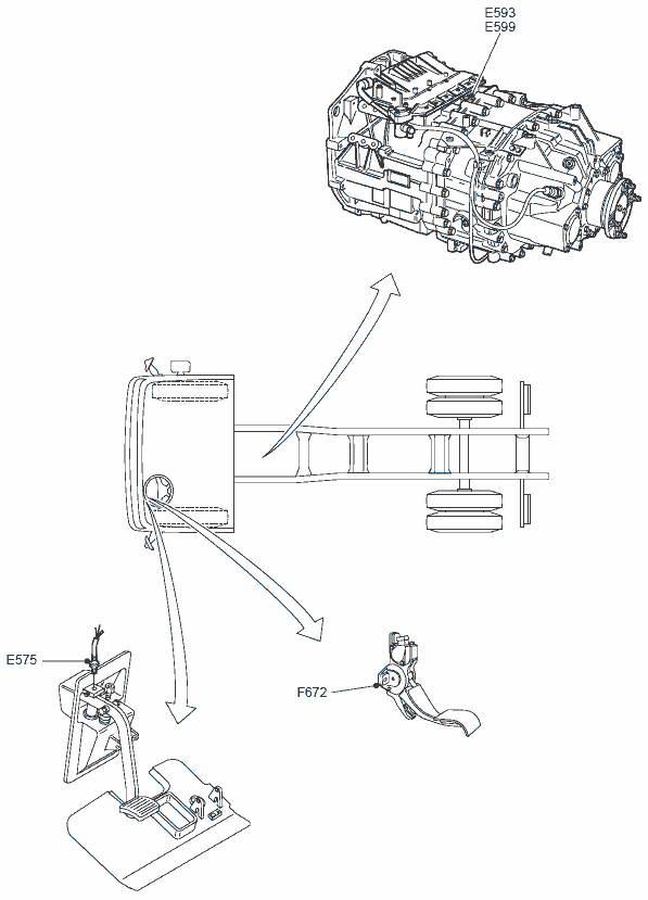
- E575 Proximity switch, clutch
- F000 Parking brake switch
- F552 Crankshaft sensor
- F558 Camshaft sensor
- F566 Coolant temperature sensor
- F649 Charge boost pressure and temperature sensor
- F672 Accelerator pedal sensor
- F713 Fuel pressure and temperature sensor
- F744 Engine oil pressure and temperature sensor
- G014 Glow relay
- G036 Stop light relay
- G126 Engine rmanagement supply relay
- G328 Engine stop relay
- G469 Brake signal relay
LOCATION OF COMPONENTS IN ENGINE


DMCI CF75IV
Block diagram i401125 applies to:
- CF75 IV, specification week <2009-24
Explanation of block diagram
- A Version with glowing system
- B Version with ABS-D
- C Version with manual gearbox
- D Version with E-FAN
- - Non-Western European driving conditions vehicles
- E Version with AS Tronic
- F Version with manual gearbox
- G Version with automatic gearbox
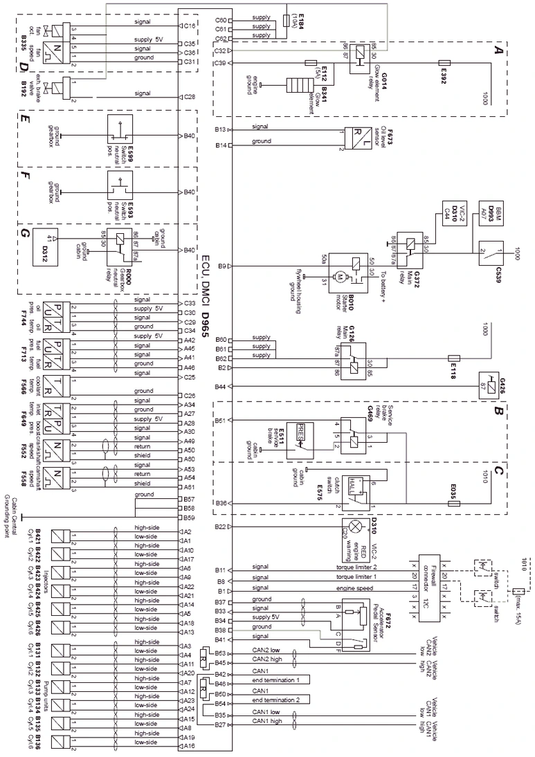
- B010 Motor, starter
- B131 Solenoid valve, pump unit, cyl. 1
- B132 Solenoid valve, pump unit, cyl. 2
- B133 Solenoid valve, pump unit, cyl. 3
- B134 Solenoid valve, pump unit, cyl. 4
- B135 Solenoid valve, pump unit, cyl. 5
- B136 Solenoid valve, pump unit, cyl. 6
- B192 Valve, exhaust brake
- B335 Clutch, electronically controlled fan
- B341 Glow element
- B421 Solenoid valve, injector, cyl. 1
- B422 Solenoid valve, injector, cyl. 2
- B423 Solenoid valve, injector, cyl. 3
- B424 Solenoid valve, injector, cyl. 4
- B425 Solenoid valve, injector, cyl. 5
- B426 Solenoid valve, injector, cyl. 6
- D310 ECU, VIC-2
- D312 ECU, AGC-A
- D965 ECU, DMCI
- D993 ECU, body builder module
- E013 Fuse, brake lights
- E112 Fuse, warning light, preheating
- E118 Fuse, engine
- E184 Fuse, engine
- E392 Fuse, pre-heating (grid)
- E511 Switch, stop lights
- E593 Switch, neutral position
- E575 Switch, clutch
- E599 Switch, neutral position
- F552 Sensor, crankshaft
- F558 Sensor, camshaft
- F566 Sensor, coolant temperature
- F649 Sensor, boost pressure and intake air temp.
- F672 Sensor, accelerator pedal
- F673 Sensor, oil level
- F713 Sensor, fuel pressure and temperature
- F744 Sensor, engine oil pressure and temperature
- G014 Relay, grid heater
- G126 Relay, power supply
- G426 Relay, contact
- G469 Relay, brake applied
- R000 Relay, neutral gear, AGC
Block diagram i401583 applies to:
- CF75 IV, specification week >2009-25
Modifications to CF75 IV
- VIC-2 (D310) replaced by VIC-3 (D358)
- Firewall connector torque limitation changed
Explanation of block diagram
- A Version with glowing system
- B Version with ABS-D
- C Version with manual gearbox
- D Version with AS Tronic
- E Version with manual gearbox
- F Version with automatic gearbox

- B010 Motor, starter
- B131 Solenoid valve, pump unit, cyl. 1
- B132 Solenoid valve, pump unit, cyl. 2
- B133 Solenoid valve, pump unit, cyl. 3
- B134 Solenoid valve, pump unit, cyl. 4
- B135 Solenoid valve, pump unit, cyl. 5
- B136 Solenoid valve, pump unit, cyl. 6
- B192 Valve, exhaust brake
- B335 Clutch, electronically controlled fan
- B341 Glow element
- B421 Solenoid valve, injector, cyl. 1
- B422 Solenoid valve, injector, cyl. 2
- B423 Solenoid valve, injector, cyl. 3
- B424 Solenoid valve, injector, cyl. 4
- B425 Solenoid valve, injector, cyl. 5
- B426 Solenoid valve, injector, cyl. 6
- D312 ECU, AGC-A
- D358 ECU, VIC-3
- D965 ECU, DMCI
- D993 ECU, body builder module
- E013 Fuse, brake lights
- E112 Fuse, warning light, preheating
- E118 Fuse, engine
- E184 Fuse, engine
- E392 Fuse, pre-heating (grid)
- E511 Switch, stop lights
- E593 Switch, neutral position
- E575 Switch, clutch
- E599 Switch, neutral position
- F552 Sensor, crankshaft
- F558 Sensor, camshaft
- F566 Sensor, coolant temperature
- F649 Sensor, boost pressure and intake air temp.
- F672 Sensor, accelerator pedal
- F673 Sensor, oil level
- F713 Sensor, fuel pressure and temperature
- F744 Sensor, engine oil pressure and temperature
- G014 Relay, grid heater
- G126 Relay, power supply
- G426 Relay, contact
- G469 Relay, brake applied
- R000 Relay, neutral gear, AGC
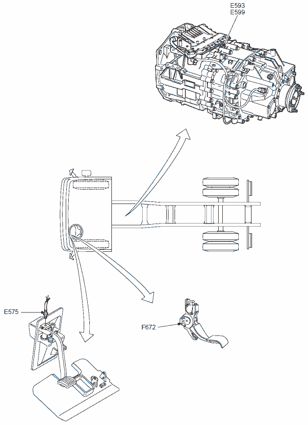
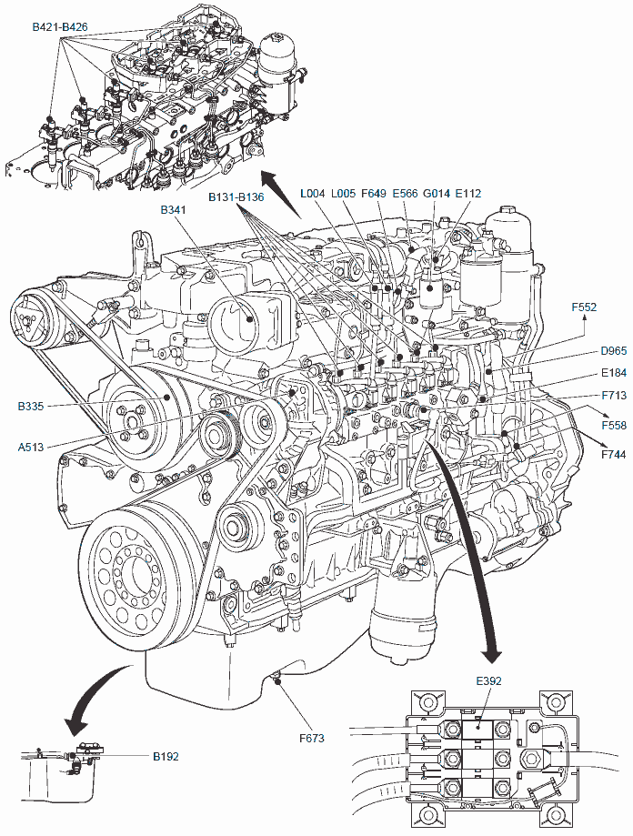
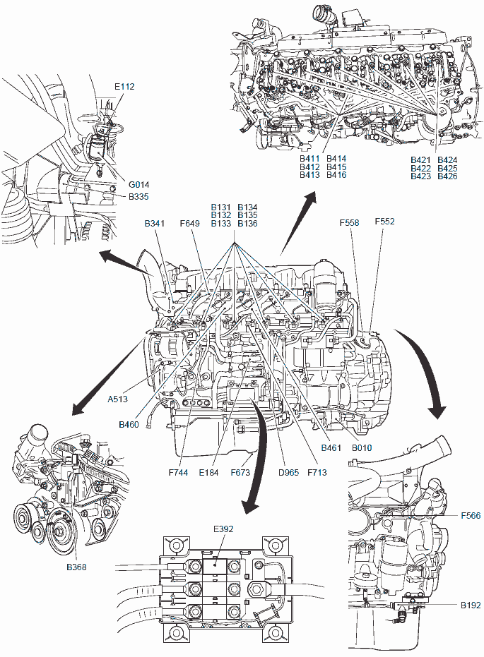
LOCATION INFORMATION, DMCI, ENGINE
LOCATION INFORMATION, DMCI, CAB AND CHASSIS

DMCI CF85IV, XF105
Block diagram i400990 applies to:
- CF85 IV
- XF105
Explanation of block diagram
- A Version with glowing system
- B Version with AS Tronic
- C Version with manual gearbox
- D Version with ABS-D
- E Version with manual gearbox
- F Version with electronically controlled fan clutch (depending on engine output, in combination with ZF intarder as standard)
- G Version with electronic waste gate control (depending on engine output)
- H Version equipped with MX Engine Brake
<2009-04
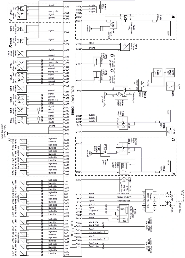
- B010 Motor, starter
- B131 Solenoid valve, pump unit, cyl. 1
- B132 Solenoid valve, pump unit, cyl. 2
- B133 Solenoid valve, pump unit, cyl. 3
- B134 Solenoid valve, pump unit, cyl. 4
- B135 Solenoid valve, pump unit, cyl. 5
- B136 Solenoid valve, pump unit, cyl. 6
- B192 Valve, exhaust brake
- B335 Clutch, electronically controlled fan
- B341 Glow element
- B368 Valve, waste-gate
- B411 Solenoid valve, MX Engine Brake, cyl. 1
- B412 Solenoid valve, MX Engine Brake, cyl. 2
- B413 Solenoid valve, MX Engine Brake, cyl. 3
- B414 Solenoid valve, MX Engine Brake, cyl. 4
- B415 Solenoid valve, MX Engine Brake, cyl. 5
- B416 Solenoid valve, MX Engine Brake, cyl. 6
- B421 Solenoid valve, injector, cyl. 1
- B422 Solenoid valve, injector, cyl. 2
- B423 Solenoid valve, injector, cyl. 3
- B424 Solenoid valve, injector, cyl. 4
- B425 Solenoid valve, injector, cyl. 5
- B426 Solenoid valve, injector, cyl. 6
- D310 ECU, VIC-2
- D965 ECU, DMCI
- D993 ECU, body builder module
- E013 Fuse, brake lights
- E112 Fuse, warning light, preheating
- E118 Fuse, engine
- E184 Fuse, engine
- E392 Fuse, preheating (grid)
- E511 Switch, stop lights
- E593 Switch, neutral position
- E575 Switch, clutch
- E599 Switch, neutral position
- F552 Sensor, crankshaft
- F558 Sensor, camshaft
- F566 Sensor, coolant temperature
- F649 Sensor, boost pressure and intake air temp.
- F672 Sensor, accelerator pedal
- F673 Sensor, oil level
- F713 Sensor, fuel pressure and temperature
- F743 Sensor, second, coolant temperature
- F744 Sensor, engine oil pressure and temperature
- G014 Relay, grid heater
- G126 Relay, power supply
- G426 Relay, contact
- G469 Relay, brake applied
LOCATION INFORMATION, DMCI, ENGINE
LOCATION INFORMATION, DMCI, CAB AND CHASSIS
Block diagram i401523 applies to:
- CF85 IV, specification week <2009-24
- XF105, specification week <2009-24
Explanation of block diagram
- A Version with glowing system
- B Version with AS Tronic
- C Version with manual gearbox
- D Version with manual gearbox
- E Version with electronically controlled fan clutch
- F Version with electronic wastegate control (depending on engine output)
- G Version with MX engine brake
>2009-05

- B010 Motor, starter
- B131 Solenoid valve, pump unit, cyl. 1
- B132 Solenoid valve, pump unit, cyl. 2
- B133 Solenoid valve, pump unit, cyl. 3
- B134 Solenoid valve, pump unit, cyl. 4
- B135 Solenoid valve, pump unit, cyl. 5
- B136 Solenoid valve, pump unit, cyl. 6
- B192 Valve, exhaust brake
- B335 Clutch, electronically controlled fan
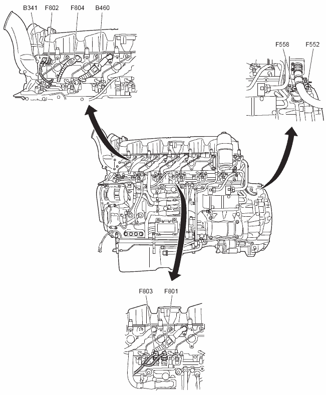
- B341 Glow element
- B368 Valve, wastegate
- B411 Solenoid valve, MX Engine Brake, cyl. 1
- B412 Solenoid valve, MX Engine Brake, cyl. 2
- B413 Solenoid valve, MX Engine Brake, cyl. 3
- B414 Solenoid valve, MX Engine Brake, cyl. 4
- B415 Solenoid valve, MX Engine Brake, cyl. 5
- B416 Solenoid valve, MX Engine Brake, cyl. 6
- B421 Solenoid valve, injector, cyl. 1
- B422 Solenoid valve, injector, cyl. 2
- B423 Solenoid valve, injector, cyl. 3
- B424 Solenoid valve, injector, cyl. 4
- B425 Solenoid valve, injector, cyl. 5
- B426 Solenoid valve, injector, cyl. 6
- D310 ECU, VIC-2
- D965 ECU, DMCI
- D993 ECU, body builder module
- E013 Fuse, brake lights
- E112 Fuse, warning light, preheating
- E118 Fuse, engine
- E184 Fuse, engine
- E392 Fuse, pre-heating (grid)
- E575 Switch, clutch
- E593 Switch, neutral position
- E599 Switch, neutral position
- F552 Sensor, crankshaft
- F558 Sensor, camshaft
- F566 Sensor, coolant temperature
- F672 Sensor, accelerator pedal
- F673 Sensor, oil level
- F801 Sensor, fuel pressure
- F802 Sensor, boost pressure
- F803 Sensor, fuel temperature
- F804 Sensor, boost temperature
- F808 Sensor, oil temperature
- F810 Sensor, oil pressure
- G014 Relay, grid heater
- G126 Relay, power supply
- G426 Relay, contact
Block diagram i401582 applies to:
- CF85 IV, specification week >2009-25
- XF105, specification week >2009-25
Modifications to CF85 IV/XF105
- Firewall connector torque limitation changed
- VIC-2 (D310) replaced by VIC-3 (D358)
Explanation of block diagram
- A Version with glowing system
- B Version with AS Tronic
- C Version with manual gearbox
- D Version with manual gearbox
- E Version with electronically controlled fan clutch
- F Version with electronic wastegate control (depending on engine output)
- G Version with MX engine brake
>2009-05

- B010 Motor, starter
- B131 Solenoid valve, pump unit, cyl. 1
- B132 Solenoid valve, pump unit, cyl. 2
- B133 Solenoid valve, pump unit, cyl. 3
- B134 Solenoid valve, pump unit, cyl. 4
- B135 Solenoid valve, pump unit, cyl. 5
- B136 Solenoid valve, pump unit, cyl. 6
- B192 Valve, exhaust brake
- B335 Clutch, electronically controlled fan
- B341 Glow element
- B368 Valve, wastegate
- B411 Solenoid valve, MX Engine Brake, cyl. 1
- B412 Solenoid valve, MX Engine Brake, cyl. 2
- B413 Solenoid valve, MX Engine Brake, cyl. 3
- B414 Solenoid valve, MX Engine Brake, cyl. 4
- B415 Solenoid valve, MX Engine Brake, cyl. 5
- B416 Solenoid valve, MX Engine Brake, cyl. 6
- B421 Solenoid valve, injector, cyl. 1
- B422 Solenoid valve, injector, cyl. 2
- B423 Solenoid valve, injector, cyl. 3
- B424 Solenoid valve, injector, cyl. 4
- B425 Solenoid valve, injector, cyl. 5
- B426 Solenoid valve, injector, cyl. 6
- D358 ECU, VIC-3
- D965 ECU, DMCI
- D993 ECU, body builder module
- E013 Fuse, brake lights
- E112 Fuse, warning light, preheating
- E118 Fuse, engine
- E184 Fuse, engine
- E392 Fuse, pre-heating (grid)
- E575 Switch, clutch
- E593 Switch, neutral position
- E599 Switch, neutral position
- F552 Sensor, crankshaft
- F558 Sensor, camshaft
- F566 Sensor, coolant temperature
- F672 Sensor, accelerator pedal
- F673 Sensor, oil level
- F801 Sensor, fuel pressure
- F802 Sensor, boost pressure
- F803 Sensor, fuel temperature
- F804 Sensor, boost temperature
- F808 Sensor, oil temperature
- F810 Sensor, oil pressure
- G014 Relay, grid heater
- G126 Relay, power supply
- G426 Relay, contact
LOCATION INFORMATION, DMCI, ENGINE 1

LOCATION INFORMATION, DMCI, ENGINE 2
LOCATION INFORMATION, DMCI, CAB AND CHASSIS