

Электрические схемы блока координатора COO7 SCANIA
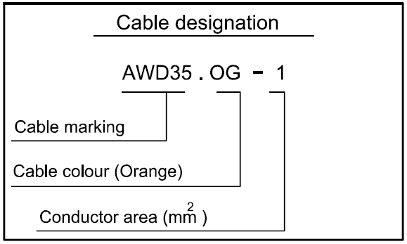
Code Colour
- BK Black
- BN Brown
- RD Red
- OG Orange
- YE Yellow
- GN Green
- BU Blue
- VT Violet
- GY Grey
- WH White
- PK Pink

- B49 С 6 Switch, manual exhaust brake
- C69 D 7 Connector 21-pole, instr p/front
- C100 В 4 Connector. 66-pole
- C113 А 5 Connector, 2-pole, ADR, engine
- C275 С 7 Joint connector, instr light
- C451 D 6 Connector. 2-pole, manual exhaust brake
- C479 D 2 Joint connector green CAN
- C480 D 3 Joint connector red CAN
- C481 D 2 Joint connector yellow CAN
- C482 F 5 Joint conncctor wake up
- C482 С З Joint connector wake up
- C483 F 6 Joint connector wake up
- C489 Е 7 Connector, 21-pole, COO
- D35 Е 5 Potentiometer, throttle pedal sensor
- D60 Е 5 Potentiometer, clutch pedal
- D61 Е 5 Potentiometer, brake pedal
- E30 Е 6 Control unit, coordinator
- Е44 А 4 Control unit, EMS
- Е49 D 3 Control unit, Immobihser
- G1 С 2 Joint connector, ground
- G2 В 7 Joint conncctor, ground
- G4 С 6 Joint connector, ground
- G15.D С 4 Ground, torpedo wall
- G15.H Е 4 Ground, torpedo wall
- К1 С 1 Diagnostics outlet
- 01 F 7 Combination instrument
- Р2 F 5 Central electric unit
- Р2 D 4 Central electric unit
- S4 F 7 Switch, starter
- S6 С 8 Switch, exhaust brake power
- S29 С 7 Switch, white smoke limiter
- S51 D 8 Switch, cruisc control/display
- S142 С 7 Switch, cruise control
- ТЗ Е 7 Monitor, applied parking brake
- Т8 С 7 Monitor, coolant level
- Т16 А 4 Sensor, fuel level
- U6 Е 8 Spring coil

- B16 В 5 Switch, reverse light
- B45 В 4 Switch, neutral
- C12 D 2 Connector, 21-p o le
- C70 С 2 Connector. 3 -p o le
- C96 С 4 Connector, 4 -pole , PT01 EK
- C100 D 6 Connector, 6 6-po le
- C101 D 4 Conncctor, 6 6 -p o |c
- C102 D 6 Connector, 6 6-po le
- C122 C 6 Connector, 7 -pole , gearbox
- C202 С 5 Splice, gearbox
- C275 D 7 Joint connector, instr light
- C428 С 2 Connector, 3-po|e
- C489 E 6 Connector, 21-p o le , COO
- E30 F 6 Control unit, coordinator
- G3 В 7 Joint connector, ground
- G4 E 2 Joint connector, ground
- G13 D 4 Ground, torpedo wall
- P2 F 8 Central electric unit
- S30 С 7 Switch, power take off, EG
- S31 С 7 Switch, power take off, EK
- S44 В 1 Switch, low/high gear split
- S63 В 2 Switch, low/high gear range
- S168 С 8 Switch. РТО ED
- V13 В 5 Solenoid valve. РТО EG single rear
- V43 В 4 Solenoid valve, power take o ff EK
- V62 В 6 Solenoid valve, low split
- V63 В 5 Solenoid valve, low range
- V77 В 6 Solenoid valve, high split
- V78 В 6 Solenoid valve, high range
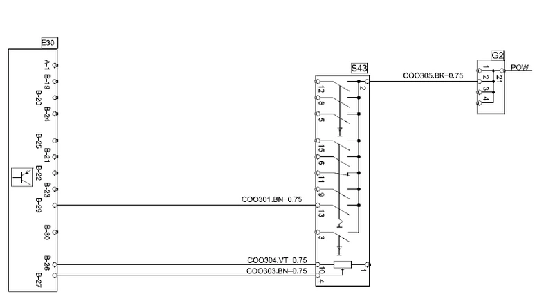
- E30 A 4 Control unit, coordinator
- G2 D 5 Joint connector, ground
- S43 С 4 Switch, retarder
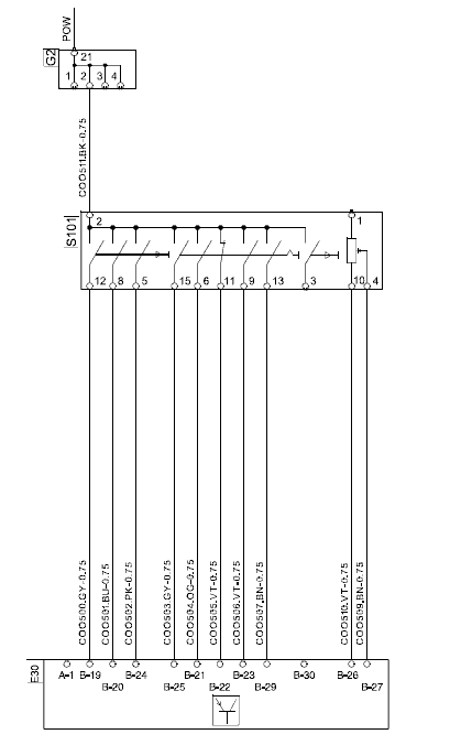
- E30 A 4 Control unit, coordinator
- G2 D 5 Joint connector, ground
- S101 D 4 Switch, driving mode

- B36 D 4 Switch, trailer brake
- С1 D 7 Connector, 66-pole
- C102 D 8 Connector, 66-pole
- C275 В 4 Joint connector, instr light
- D54 D 4 Resistor unit, limited hand throttle
- E30 F 5 Control unit, coordinator
- G2 D 5 Joint connector, ground
- G4 D 3 Joint connector, ground
- G13 D 8 Ground, torpedo wall
- G22.D D 7 Ground, cab front
- Р2 C 3 Central electric unit
- S134 С 4 Switch, limited hand throttle
- S135 С 4 Switch, limited hand throttle
- Т18 С 8 Monitor, low pressure
- Т55 С 7 Monitor, flow, circuit 1
- Т56 С 6 Monitor, flow, circuit 2