
TATA Daewoo DX12 E6 TDCV
Руководство по поиску и устранению неисправностей
TABLE OF CONTENTS
1. Fault code definition
2. Torque reduction by fault
3. Torque reduction by Coolant / Fuel / Inlet air temperature
4. Electric fault troubleshooting guide tip
5. Fault list summary
6. Troubleshooting guide
The fault code is defined according to SAE J2012, J1939 standard.
1) SAEJ2012
Example : P0002
P : Power train (Used)
C : Chassis (Not used)
B : Body(Not used)
U : Network (Used)
0002 : Fault numbers
2) SAEJ1939
Example : E000027-01
E : Engine (Not visible)
000027 : SPN 6-digit (Suspect Parameter Numbers)
01 : FMI 2-digit (Failure Mode Identifier)
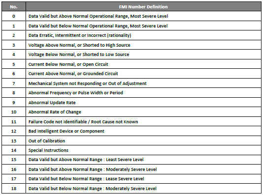
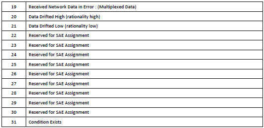
• The FMI defined in the standard is divided into the following types. But some faults that could not be defined or duplicated were used to similar or reserved number.
Torque reduction by fault
Each monitored parameter that uses the de-rate function has its own de-rate trigger threshold. If the
de-rate threshold is equal to or exceeded by any parameter for a de-rate protection will be set active, the engine will de-rate.
Each application has different engine full load. So following is the picture showing some example of
engine torque de-rates.
1) Torque reduction levell (Mild) - The maximum engine torque is limited by 70% of machine full load curve.
2) Torque reduction level2 (Severe) - The maximum engine torque is limited by 50% of machine full load curve.

Torque reduction by Coolant / Fuel / Inlet air temperature
If the engine coolant temperature over the 110degC, the engine torque will be reduced progressively
If the engine fuel temperature at High pressure pump inlet(Fuel filter) over the 80degC, the engine
torque will be reduced progressively
If the engine is on the high ambient temperature, the engine torque will be reduced progressively for
anti-fouling of turbocharger.
Electric fault trouble shooting guide tip
Electronic problems can be caused by many causes. Therefore, it is not possible to list all the causes,
but it is usually necessary to check the following items.
1) Check the battery
A. check Terminal tightening.
B. check absence of oxidation
C. check absence of consumers
- Check if there is any device that is not supplied by the engine or machine company capable of generating dark current installed.
D. check battery capacity
E. check battery external damage
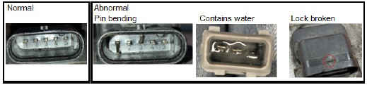
2) Check part's connection (ECU, VCU, sensor etc.)
A. check pin condition (bending, broken, breakaway)
B. check terminal condition (widening, broken, breakaway)
C. check absence of oxidation
D. check absence of contains water
E. check external damage
F. check looseness of assembly connection
- Except some specific sensors(CAM, Crank, etc...), ECU can diagnosis the open circuit at Key on condition. Check if the open circuit fault is occurred due to contact failure when the wiring harness is wiggled by hands.
G. check cross-connect with another sensor
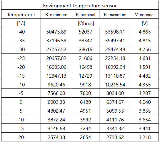
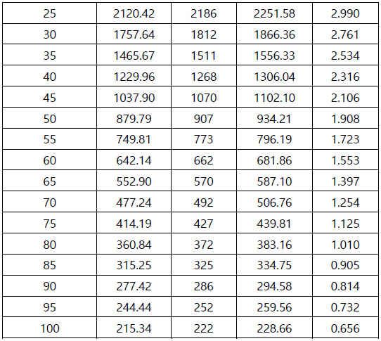
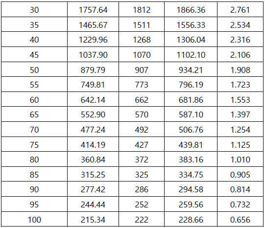
3) check sensor resistance
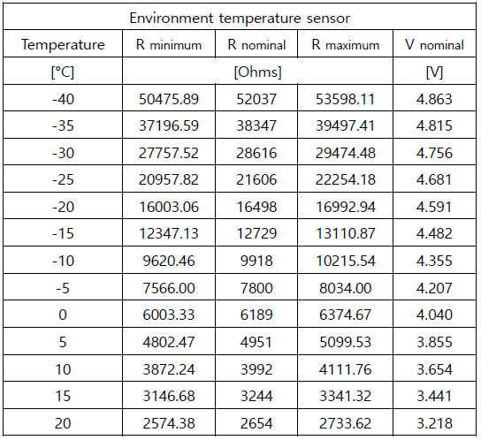
A. Resistance type sensor only (for example temperature sensor)
B. remove sensor connector and check sensor itself resistance
- refer each resistance information
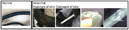
4) Check wire harness
A. check pin to pin. (sensor connector to ECU connector)
B. check damage of wire. (broken, cut)
5) Check Network
A. check the service tool connect ability
B. resistance of CAN high and CAN low (CAN line has 120ohm resistors at both ends)
C. check voltage by 2 channel oscilloscope
- CAN High and CAN low signal are balanced when one is up, the other is down.
- CAN High signal is 2.5~3.5V and CAN Low signal is 1.5~2.5V
* For the CAN pin number, refer to the Diagnostic connector.
6) Check CAM CRANK (Oscilloscope)
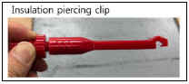
A. Preparing oscilloscope and Insulation piercing clip
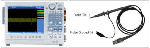
i. Oscilloscope setting
1. Sampling interval: 2MHz, input signal voltage +/- 30V
2. Channel : at least 2 channel (CAM and CRANK)
ii. Oscilloscope and Probe (example)
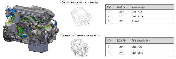
B. Check the CAM and CRANK sensor location and Pin information
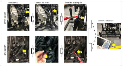
C. Installation step
1. Remove the connection cover
2. Install the piercing clip (CAM and CRANK)
3. Connect probe each clip
D. Measuring step
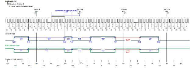
1. Measuring CAM and CRANK signal at same time Example)
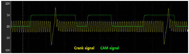
2. Inspection the signal (focus at CRANK signal tooth depend on CAM rising edge and falling edge)
Example)


Все коды неисправностей в "Большой энциклопедии для автоэлектриков и диагностов"
Fault Code Fault Name
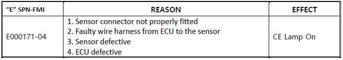
P0071 High environment temperature error
1) Overview
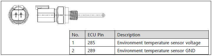
2) Component Location
The sensor is not specifically positioned (usually located around the supply module and DEF supply line).
3) Condition for Running Diagnostic
Key ON or Engine running
4) Condition for Setting the Fault Code
If Environment temperature is greater than 130°C for 0.5 second.
5) Condition for Clearing the Fault Code
If Environment temperature is less than or equal to 130 C for 0.05 second.
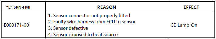
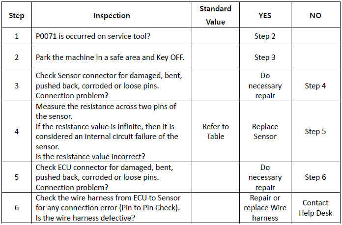
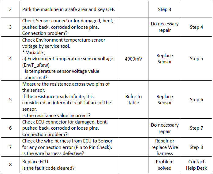
6) Check List
Fault Code Fault Name
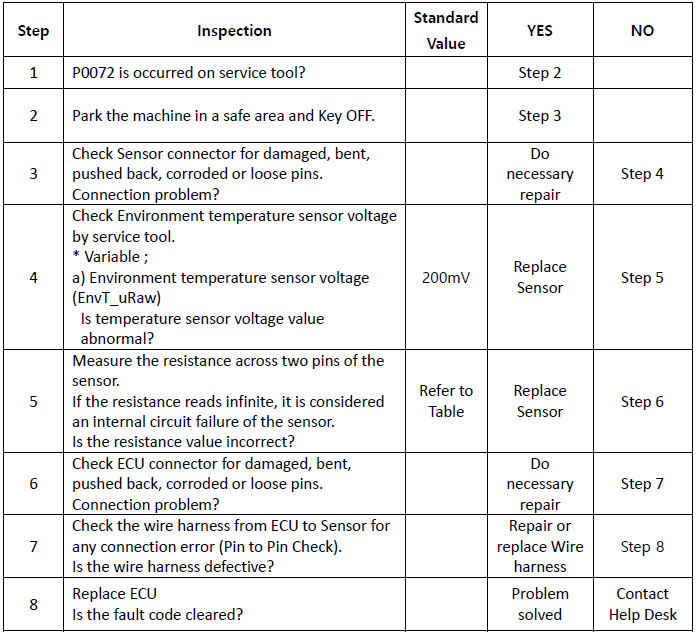
P0072 Low voltage error for environment temperature sensor
1) Overview
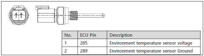

2) Component Location
The sensor is not specifically positioned (usually located around the supply module and DEF supply line).
3) Condition for Running Diagnostic
Key ON or Engine running
4) Condition for Setting the Fault Code
If Environment temperature sensor voltage is less than 200 mV for 0.05 second,
5) Condition for Clearing the Fault Code
If Environment temperature sensor raw voltage is greater than or equal to 200 mV for 0.05 second,
6) Check List
Fault Code Fault Name
P0073 High voltage error for environment temperature sensor

1) Overview
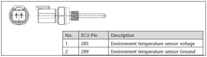
2) Component Location
The sensor is not specifically positioned (usually located around the supply module and DEF supply line).
3) Condition for Running Diagnostic
Key ON or Engine running
4) Condition for Setting the Fault Code
If Environment temperature sensor voltage is greater than 4900 mV for 0.05 second.
5) Condition for Clearing the Fault Code
If Environment temperature sensor voltage is less than or equal to 4900 mV for 0.05 second,
6) Check List

Fault Code Fault Name
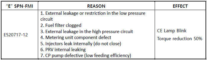
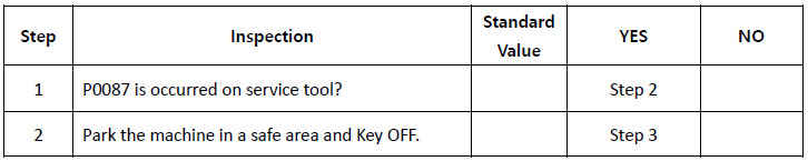
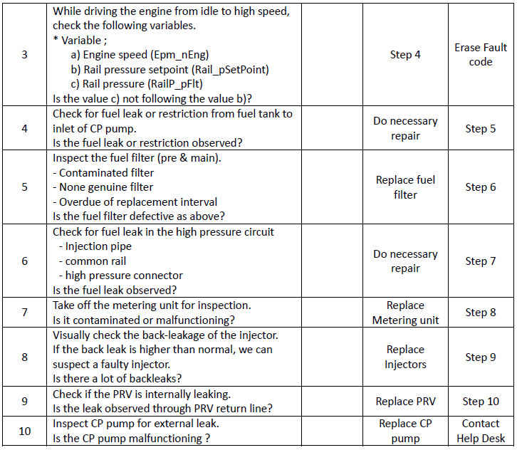
P0087 Rail pressure below minimum limit error

1) Overview
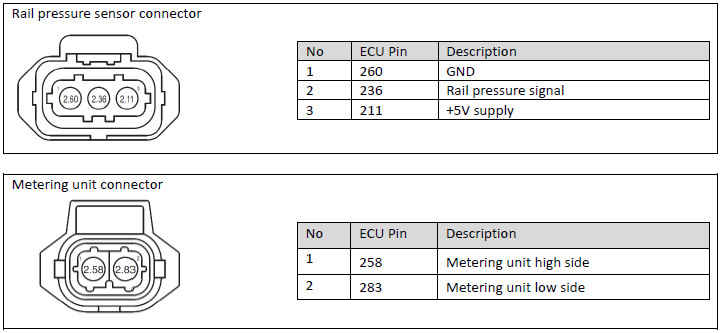
2) Component Location

3) Condition for Running Diagnostic Engine running
4) Condition for Setting the Fault Code If Rail pressure (RailP_pFlt) is less than 200 bar for 2.5 seconds,
5) Condition for Clearing the Fault Code If Rail pressure is operating normally.
The fault code is not cleared at the current driving cycle once occurred.
At the next driving cycle, with no condition of setting the fault code achieved, the fault will become a historical one to be cleared.
6) Check List
Продолжение смотри в