
Electronic systems Actros model 963
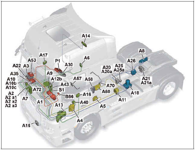
Illustrated on model 963.4
A1 Instrument cluster (ICUC) control unit
A2 Central gateway control unit (CGW)
A2 a1 Central data memory (CDS)
A2 a2 Communications interface (COM) control unit
A2 a3 Maintenance system (MS) control unit
A3 Drive control (CPC) control unit
A4 Engine management control unit (MCM)
A5 Transmission control (TCM) control unit
A6 Anti>theft alarm system (ATA) control unit
A7 Cab signal acquisition and actuation module control unit (SCA)
A8 Frame signal acquisition and actuation module control unit (SCH)
A9 Truck Control Center (TCC)
A10 Antilock brake system (ABS) control unit, 4>channel
A10b Electronic brake control (EBS) control unit (Wabco)
A10c Electronic brake control (EBS) control unit (Knorr)
A11 Retarder control (RCM) control unit
A12b Heating, ventilation and air conditioning control unit (HVAC)
A13 Truck auxiliary heater (ITH) control unit
A14 Stationary air conditioning (IAC) control unit
A15 Front radar sensor (RDF) control unit
A16 Driver door module (DCMD) control unit
A17 Front passenger door module (DCMP) control unit
A18 Electronic Air Processing Unit (EAPU) control unit
A20 Front axle axle modulator (Wabco)
A20a Front axle axle modulator (Knorr)
A21 Rear axle axle modulator (Wabco)
A21a Rear axle axle modulator (Knorr)
A22 Parameterizable special module (PSM) control unit
A25 Electronic Stability Program (ESP“) control unit (Wabco)
A25a Electronic Stability Program (ESP“) control unit (Knorr)
A26 Level control (CLCS) control unit
A30 FleetBoard“ control unit
A35 Tire pressure monitor (TPM) control unit
A40 Supplemental restraint system (SRS) control unit
A43 Modular switch panel (MSF) control unit
A53 Driver assistance system (VRDU) control unit
A57 EATU output NOx sensor control unit
A58 SCR control unit
A60 Exhaust aftertreatment (ACM) control unit
A70 EATU input NOx sensor control unit
A72 Lane Assistant camera
B66 Steering wheel angle sensor (SAS)
P1 Tachograph (TCO)
S1 Electronic ignition lock (EIS)
A1 Instrument cluster (ICUC) control unit
A2 Central gateway control unit (CGW)
A2 a1 Central data memory (CDS)
A2 a2 Communications interface (COM) control unit
A2 a3 Maintenance system (MS) control unit
A3 Drive control (CPC) control unit
A4 Engine management control unit (MCM)
A5 Transmission control (TCM) control unit
A6 Antitheft alarm system (ATA) control unit
A7 Cab signal acquisition and actuation module control unit (SCA)
A8 Frame signal acquisition and actuation module control unit (SCH)
A9 Truck Control Center (TCC)
A10 Antilock brake system (ABS) control unit, 4>channel
A10b Electronic Brake Control (EBS) control unit (Wabco)
A10c Electronic Brake Control (EBS) control unit (Knorr)
A11 Retarder control (RCM) control unit
A12b Heating, ventilation and air conditioning control unit (HVAC)
A13 Truck auxiliary heater (ITH) control unit
A14 Stationary air conditioning (IAC) control unit
A15 Front radar sensor (RDF) control unit
A16 Driver door module (DCMD) control unit
A17 Front passenger door module (DCMP) control unit
A18 Electronic Air Processing Unit (EAPU) control unit
A20 Front axle axle modulator (Wabco)
A20a Front axle axle modulator (Knorr)
A21 Rear axle axle modulator (Wabco)
A21a Rear axle axle modulator (Knorr)
A22 Parameterizable special module (PSM) control unit
A25 Electronic Stability Program (ESP“) control unit (Wabco)
A25a Electronic Stability Program (ESP“) control unit (Knorr)
A26 Level control (CLCS) control unit
A28 Driver switch group
A30 FleetBoard“ control unit
A33 Battery disconnect switch control unit (BESO)
A34 Additional steering axle (ASA) control unit
A35 Tire pressure monitor (TPM) control unit
A40 Supplemental restraint system (SRS) control unit
A43 Modular switch panel (MSF) control unit
A53 Driver assistance system (VRDU) control unit
A54 Lower radiator shutters controller unit
A55 Upper radiator shutters controller unit
A57 EATU output NOx sensor control unit
A58 SCR control unit
A60 Exhaust aftertreatment (ACM) control unit
A70 EATU input NOx sensor control unit
A72 Lane Assistant camera
B42 Alarm siren
B43 Interior protection sensor
B66 Steering wheel angle sensor (SAS)
B81 Rain and light sensor (RLS)
CAN 1 Exterior>CAN
CAN 2 Interior CAN
CAN 3 Frame CAN
CAN 4 Drive train CAN
CAN 5 Climate control CAN
CAN 6a Front axle brakes CAN
CAN 6b Rear axle brakes CAN
CAN 6c Redundant brakes CAN
CAN 6d ESP“ brakes CAN
CAN 7 Trailer CAN (PSM)
CAN 8 Body manufacturer CAN (PSM)
CAN 9 Telematics CAN
CAN 10 Diagnostic CAN
CAN 11 Trailer CAN (EBS)
CAN 12 Radar CAN
CAN 13 NOx>CAN
G1a Battery sensor (IBS)
LIN 1 Rain/light sensor LIN
LIN 2 Battery sensor LIN
LIN 3 Right multifunction control lever LIN
LIN 4 Left multifunction control lever LIN
LIN 5 Radiator shutters LIN
LIN 6 LIN SCA/SCH redundancy
LIN 7 Button group LIN
LIN 8 Level control LIN
LIN 9 Driver switch panel LIN
LIN 10 EAPU>LIN
LIN 11 ATA>LIN
P1 Tachograph (TCO)
S1 Electronic ignition lock (EIS)
S20 Left multifunction control lever
S22 Level control operating unit
S23 Right multifunction control lever
S110 Left multifunction steering wheel button group
S111 Right multifunction steering wheel button group
X100.16 Diagnostic socket
X102.15 Trailer socket 15>pin
X103.7 ABS trailer socket 7>pin
X167.12 Fleet management system electrical connector
X910 Electrical connector for body manufacturers
XR>E1H CAN>H exterior cable weld point 1
XR>E1L CAN>L exterior cable weld point 1
XR>E1M CAN>ground exterior cable weld point 1
Z1 Cab instrument panel CAN bus star point
Z3 Frame CAN bus star point
Z4 Drive CAN bus star point ASIC ASIC data bus (Application System Integrated Circuit)
1 General
The increase in electronic systems in the new Actros means that more and more signals now have to be made available across all the systems. This primarily has an impact on the networking, which has also gained in complexity. Alongside the familiar CAN and ASIC data bus systems the LIN data bus is now increasingly being used. The new Actros alone has 11 LIN data buses, which connect the various control units, switches or other electronic components to each other. The number of CAN data buses by contrast has only risen slightly.
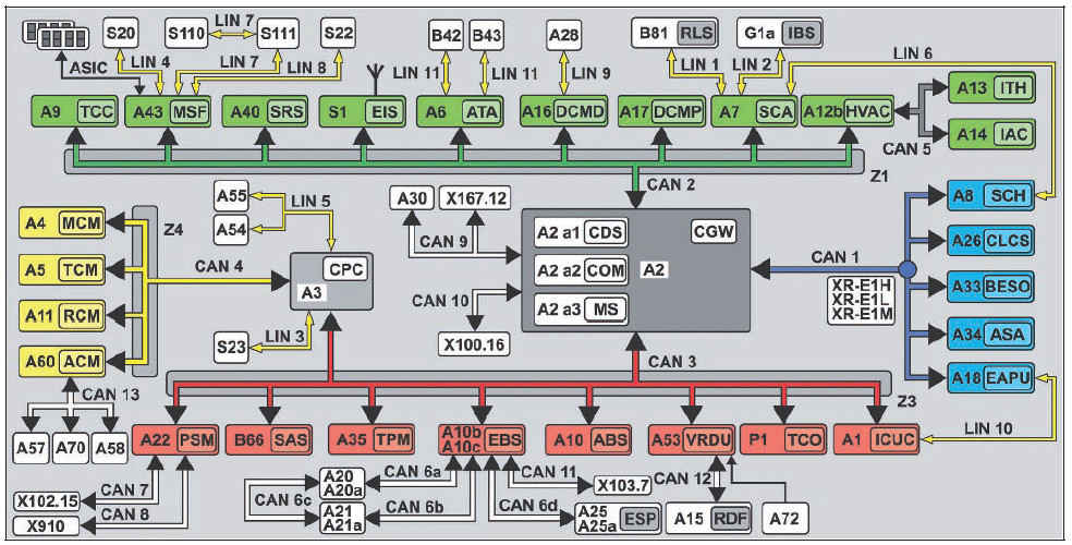
2 CAN data bus system
The CAN data bus system enables information to be exchanged quickly and reliably between control units over only a few lines.
The information is sent or received successively (serial). The exchange is bidirectional, i.e. each control unit operates as both a
transmitter and a receiver.
2.1 Transfer rates
In the new Actros up to 13 different CAN data buses are used. The majority of these CAN data buses have a transfer rate of >250 kBaud and this classes them as high>speed CAN data buses. The reasons for the increase in high>speed CAN data buses are:
• Increase in data rate (number of messages that are sent)
• Almost identical manufacturing costs as for low>speed CAN
data buses
• Greater use of LIN data bus in non>critical safety areas
• Shortening of flash or parameterization times, in particular through increase in transfer rate for diagnostic CAN (CAN 10)
The following CAN data buses have a transfer rate of 500 kBaud:
• Exterior CAN (CAN 1)
• Interior CAN (CAN 2)
• Frame CAN (CAN 3)
• Climate control CAN (CAN 5)
• Front axle brake CAN (CAN 6a)
• Rear axle brake CAN (CAN 6b)
• Redundancy brake CAN (CAN 6c)
• Brake CAN ESP“ (CAN 6d)
• Diagnostic CAN (CAN 10)
• Radar CAN (CAN 12)
The transfer rate of the drive train CAN (CAN 4) was increased to 667 kBaud, because the high number of messages had significantly increased the bus operating rate. If the data rate was not increased, then there is the risk that some messages with low priority could no longer be sent due to the bus operating rate.
To ensure that freight forwarders, for example for fleet management, can continue to call up specific information on vehicle location, current speed, etc. the transfer rate of the telematics CAN (CAN 9) has been retained at 250 kBaud.
The transfer rates have also been retained on the trailer CAN (PSM) (CAN 7), the body manufacturer CAN (PSM) (CAN 8) and the trailer CAN (EBS) (CAN 11). They are 125 kBaud, whereby they are still classified as low>speed CAN data buses.
The transfer rate for the NOx>CAN (CAN 13) has not been changed either and is > as before > 250 kBaud.
2.2 Gateways
To compensate for the different transfer speeds, some control units also act as a gateway:
• The central gateway control unit (CGW) (A2) routes the respective messages from the exterior, interior, frame, telematics and diagnostic CAN (CAN 1, 2, 3, 9 and 10).
• The modular switch panel (MSF) control unit (A43) acts as a gateway between the interior CAN (CAN 2), the ASIC data bus (ASIC) and the three LIN data buses to the button groups on the multifunction steering wheel, the left multifunction control lever and the level control operating unit.
• The Electronic Brake Control (EBS) control unit (A10b) or (A10c), depending on the version, sends the messages from the frame CAN (CAN 3) to the front axle brake CAN (CAN 6a), the rear axle brake CAN (CAN 6b), the brake CAN ESP“ (CAN 6d) as well as, where applicable, the trailer CAN (EBS) (CAN
11) and vice versa.
• The drive control (CPC) control unit (A3) acts as an interface between the frame CAN (CAN 3) and the drive train CAN (CAN 4).
2.3 CAN neutral points and bus terminating resistors
Because of the high transfer rates on high>speed CAN data buses, there may be some reflections in the lines. Bus termination resistors are used to avoid reflections that would lead to the falsification of actual information. The characteristic impedance of the electrical line is important for the bus termination resistor.
The total bus terminating resistor on a high>speed CAN data bus is 60 ].
In the neutral points for the cab instrument panel CAN bus (Z1) and frame CAN bus (Z3) the bus terminating resistors are integrated into the neutral points. The drive CAN bus neutral point (Z4) only includes those ferrite elements that are also installed in the neutral points for interference suppression of high>frequency interference pulses.
The bus terminator on the exterior CAN (CAN 1) is realized by using bus terminating resistors within the central gateway control unit (CGW) (A2) and the Electronic Air>Processing Unit (EAPU) control unit (A18). Located in both control units is a 120 ] resistor each. The parallel connection then yields a total bus terminating resistance of 60 ].
In the diagnostic CAN (CAN 10) the bus terminator is realized by a 60 ] resistor in the central gateway control unit (CGW) (A2).
3 LIN data bus
The LIN data bus is an inexpensive serial subbus, which replaces the CAN data bus in the area of uncritical data transfer. The voltage supply for the LIN data bus is 12 V. This is realized internally in the control units through voltage dividers. Signals are transmitted through a single>wire line. The max. data rate is 20 kBaud. Communication refers to ID>based communication. All subscribers connected to the LIN data bus receive the message, but only one subscriber responds to it.
A LIN data bus subscriber never sends information by itself, as is the case, for example with a CAN data bus subscriber. Subscribers of the LIN data bus only ever respond to a query.
4 ASIC data bus system
The previously familiar ASIC data bus system is also used in the new Actros.
The ASIC data bus (ASIC) belongs to the so>called subbuses. In contrast to conventional switches which switch via their own contacts and are connected to their components via separate electrical lines (e.g. motors, solenoid valves, switch inputs, lighting devices), the ASIC data bus performs these tasks.
The electronics installed in the ASIC signal switches notifies the modular switch panel (MSF) control unit (A43) the following via the ASIC data bus (ASIC):
f switch position (open, closed, operated, not operated)
f Functionality (normally closed contact, normally open contact, changeover contact)
f System affiliation (e.g. headlamp cleaning system button, power take>off 1 button, etc.)
Each ASIC signal switch is connected over three contacts (pins) to the ASIC data bus (ASIC), and it is evaluated by the modular switch panel (MSF) control unit (A43). It is thus possible to install each ASIC signal switch at any arbitrary point on the individual switch modules.
For currents up to a maximum of 20 A there continues to be load switches which as before switch via their own contacts and are connected to their components through electrical lines.
These load switches are only connected to the switch panel via the ASIC contacts for separate background lighting.
5 Virtual control units
Virtual control units are not equipped with their own housing.
They are integrated into the hardware and software of other control units. In Star Diagnosis and the instrument cluster control unit (ICUC) (A1) they appear as independent control units.
Among the virtual control units are the central data memory (CDS) (A2 a1), the communications interface (COM) control unit (A2 a2) and the maintenance system (MS) control unit (A2 a3), which are all integrated into the central gateway control unit (CGW) (A2).
With the aid of the central data memory (CDS) (A2 a1) the parameters for the electronic control units can be reset to manufacturer default settings.
6 Safety strategy
Several control units have a redundant connection over LIN or CAN data buses. The redundant connection serves as an emergency communication, if the actual CAN connection malfunctions. The use of redundant LIN or CAN data buses is dependent on the safety relevance of each system.
The service brake system, for example has a redundant CAN data bus connection between the axle modulators.
LIN data buses serve as redundancies between the sensor and actuator module, cab (SCA) control unit (A7) and the sensor and actuator module, chassis (SCH) control unit (A8) as well as between the instrument cluster control unit (ICUC) (A1) and the Electronic Air>Processing Unit (EAPU) control unit (A18).
Продолжение и полное описание в "Большой энциклопедии для автоэлектриков и диагностов"