
FOTON AUMAN BJ3253
Диагностика неисправностей и и техническое обслуживание
Fault Diagnosis Process
Check a faulty circuit in the following steps:
1. Confirm the contents of the customer’s complaint
In order to ensure proper maintenance, confirm the fault symptoms described by the customer.
Carefully check the associated components to confirm the symptoms and make records. Breaking down of any component before confirmation of the scope and causes of the fault is not allowed.
2. Read circuit diagram and analyze cause
Analyze the entire circuit of a subsystem circuit diagram of a faulty component from the power supply to its grounding, judge and check the maintenance operation solution. If you cannot check the maintenance operation solution, refer to the description in the relevant sections of the
maintenance manual of the system and understand the principle of work. And you also need to check any other circuit used together with the faulty circuit, for example, refer to such system circuit as the fuse, grounding, switches, etc, used together on the circuit diagram. Check any
shared circuit not checked in Step 1. If other components in the shared circuit work properly, the fault must be in this circuit. If all the components on the shared circuit are at fault, the fuse or the grounding circuit may be at fault.
3. Check the circuits and components
Any circuit diagram should be used at any time together with its maintenance manual. Refer to the check steps in the diagnostic part of the maintenance manual. For a module control circuit, the components must be tested with the help of a diagnostic device. Effective fault diagnosis should be a logical and reasonable process of operation. Start checking from the most vulnerable components which can be most easily checked in accordance with the fault diagnosis process in the diagnostic sections of the maintenance manuals.
4. Fault maintenance
In case a fault is detected, refer to the description about trouble shooting in the circuit diagram and the maintenance manual, for example, the solution for poor grounding, the treatment for wiring harness connectors, etc.
5. Confirm the status of the circuit operation
After trouble shooting and when it is sure that any fault has been solved, re-check to confirm whether all the functions have been restored to normal. In case of a fuse failure, check all the circuits those share this fuse.
Electrical Fault Diagnosis and Maintenance and Caution
Disconnection of a Battery
1. Confirm that all electrical equipment is turned off
2. Turn off the battery brake switch
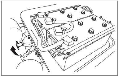
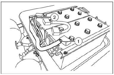
3. Disconnect the battery cables
(a). Disconnect the battery grounding cable 1.
(b). Disconnect the positive battery cable 2.
Caution:
The battery grounding cable should be disconnected first. A short circuit may occur if the positive battery cable is disconnected first.
4. Connect the battery cables in the reverse order when disconnecting them
Caution:
Clean up the battery armatures and the cable connectors. After installation is complete, apply a thin coat of grease on the battery armature to prevent corrosion of the armature and connectors.
Inspection of the fuses
Caution:
DO NOT replace a blown fuse with a new one of different rated current, as this will result in electrical fire, or cause other serious circuit damage.
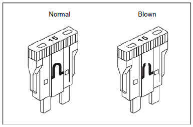
1. Low and medium-load fuses
• Fuse is the most common form of electrical protection for auto circuit. It is arranged in series in the circuit under its protection. And this fine wire or metal filament will be blown off according to the design and lead to current interruption when the current in the circuit is
overloaded (such as a ground wire short circuit). This prevents high-strength surge from reaching other parts of the circuit, thus avoiding damage. Before replacing a fuse, the cause of overload must be determined. The rated current of the new fuse must the same as that of the old one to be replaced. Blown fuse is easily identified, as shown in the figure.
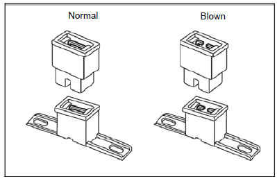
2. High-load fuse
• A high-load fuse is used in circuit of high current (starter) or anywhere the use of an ordinary fuse is impractical. Excessive current will melt the fuse strip in the fuse.
The current is then interrupted in such a case to avoid fire or circuit damage caused by heat. Before replacing a fuse, be sure to determine the cause of the formation of the excessive current. The rated current of the new fuse must the same as that of the old one to be replaced. Blown fuse is easily identified, as shown in the figure.
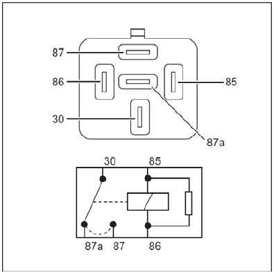
Inspection of the relay
Caution:
DO NOT replace a broken relay with a new one of different rated current.
1. 24 V relay.
• As the power supply and the load require a switch to be installed with some distance from them. This means that the wire will be longer, the voltage drop will be higher, and the relay can reduce the length of the cable between the power supply and the load, thus reducing the
voltage drop between them. Most switches cannot withstand a high passing current, the switch controls the work of the load through the control relay, so that the amperage of the current through the switch will be lower.
• Model: 24V 30/20A.
Operation of the Connector
1. Disconnect the connectors
(a). Some connectors are provided with retainer springs for fixing the connectors firmly together when the vehicle is in motion. Some retainer spring can be released by pulling towards yourself, see 1 And some retainer springs may be released by pressing forward, see 2
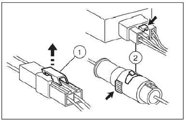
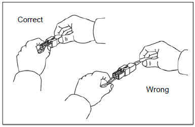
(b). Confirm the type of the retainer spring on the connector you operate. Firmly grasp the two sides of (plug and jack) of the connector.
Release the retainer spring, and carefully pull open the connector ends. DO NOT separate the connector through pulling the wire, otherwise the wire will be broken.
2. Connect the connector
(a). Please firmly grasp both sides of the connector (plug and jack). Ensure that the connector pins and the pin holes match each other. Ensure
that both sides of the connector are aligned.
Carefully push both sides of the connector together tightly until a clear clicking sound is heard.
3. Check the circuit from the connector
(a). Check the circuit with a multimeter. Insert a test probe from one side of the connector.
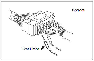
(b). Test the circuit from the open end of the connector.
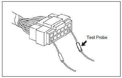
Caution:
DO NOT test the circuit by inserting a test probe whose pin hole with the diameter greater than that of the pin hole in the open end of the connector.
This will break or crack the terminal of the socket connect and/or enlarge the pin hole.
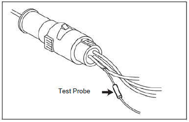
(c). Keep the connector disconnected, and insert a fine steel needle type test probe clamp into the wire to check the circuit in case the test probe cannot be inserted into a waterproof connector.
Caution:
Use special circuit check and test probe clamp tools, otherwise the wire is apt to be damaged.
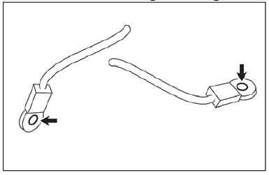
4. Dismantle the connector pin
(a). Type of the shell retainer spring:
• Insert a slender rod into the open end of the connector shell.
• Push up the retainer spring (in the direction of the arrow in Figure). Pull out the wire and the pin from the wire side of the connector.

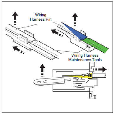
(b). Type of the pin retainer spring.
• Insert the slender rod into the open end of the connector shell.
• Flatten the retainer spring (toward the wire side of connector). Pull out the wire and the pin from the wire side of the connector.

5. Install the connector pin
(a). Check whether the retainer spring is completely upward.
(b). Insert the pin from the wire side of the connector, and push in the pin until the retainer spring clamp tightly.
(c). Gently pull the wire, and make sure that the connector pin is fixed in place.

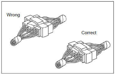
Fixing of the Wiring Harness
1. Do not clamp or squeeze the wiring harness when installing a component. All the electrical connectors must be kept clean and fixed.
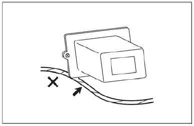
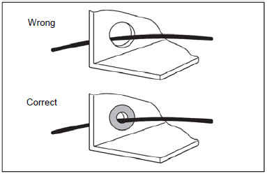
2. A grommet or a protection tube may be used to avoid the contact of the wiring harness with any sharp edge or surface.
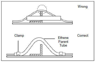
3. When placing the wiring harness, make sure that there is sufficient clearance between the wiring harness and any other component, and protect the wiring harness with an ethene parent tube and a clamp to avoid direct contact.
4. Wiring harness between the engine and the chassis should have sufficient length to prevent vibration caused by a variety of wear or damage.
Repair of the wire
1. Open the wiring harness
• If the wiring harness is stuck by tape, remove the tape. Carefully cut the wiring harness open to avoid damage to the wire insulation. If the wiring harness has plastic casing, it is only necessary to pull out the wire.
2. Cut the wire
• At the beginning, as little as possible wire should be cut from the wiring harness. And then, if you decide to cut longer wire to change the connector position, an extra length may need to be retained to adjust the connecting position to ensure that a proper clearance is kept between each connecting point and any other connecting point, wiring harness branch or joint.
3. Strip the insulating layer
• Only a wire of the same diameter is allowed to be used for replacing an old one.
Check whether there is a crack or a cut strand in the stripped wire. If the wire is damaged, replace with a new one of the same core length as that of the old one.
4. Connect the wire
• Overlap the exposed parts of two wires together, twist the wire or use a wire connecting clamp to clamp the exposed parts of the wire together. Make sure that the wire is twisted or clamped tightly.
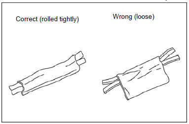
5. Wrap the wire
(a). Insert a piece of connector tape between and roll up tightly. The electric tape must cover the entire connector. Wind enough tape around the connector, and the thickness of the insulating layer must be doubled. The electric tape must be tight; otherwise the insulating capacity will
not be sufficient enough, and the loose wire may be twisted together with other wires in the wiring harness.
Grounding
1. Dismantle the grounding bolt
2. Clean the contact surfaces of the grounding rings at the wiring harness side (including vehicle body side and the bolt side) with coarse emery cloth, until the oxide is completely removed.
3. Clean the vehicle body side and the grounding point with coarse emery cloth, until the surfaces are completely clean.
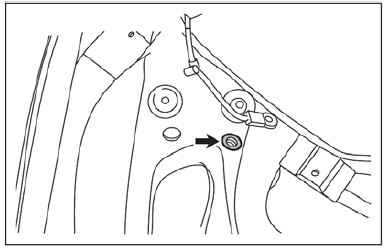
4. Re-install the grounding wire wiring harness and the fixing bolts, and tighten them with the required torque.
Fault Detection
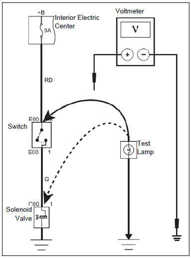
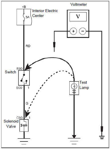
Voltage Detection
Hint: The purpose of voltage detection is to check whether there is voltage at a certain point. It is unnecessary to break down the wire connector when checking a terminal of the wire connector. You may insert the probe of the positive cable in the circuit check tool into the back of the wire connector to test.
1. First, connect the negative electrode of the check tool with the negative electrode of the battery when testing the voltage with a test lamp or voltmeter.
2. Then connect the other end of the wire of the test lamp or voltmeter with the test position.
3. If the test tool is a voltmeter and the displayed value is 1 V or more less than the specified value, the circuit is faulty. If the test tool is a test lamp and the lamp does not shed light, the circuit is faulty.
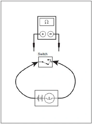
Open Circuit Test
1. Disconnect the negative wiring harness of the battery.
2. Connect a wire of a self-powered test lamp or resistance meter with the component to be tested. In case of a resistance meter, connect the two wires of the resistance meter in short circuit, zeroize the resistance meter with a zeroizer.
3. Connect another wire of the detector with the other terminal of the load to be checked.
4. If the self-powered test lamp sheds light, it means that the circuit is through; in case of a resistance meter, if the resistance is very low or close to 0 Ω, it means that the component is in good conducting state.
Short Circuit Test
1. Disconnect the negative wiring harness of the battery.
2. Connect one wire of the self-powered test lamp or resistance meter with the output terminal of the fuse.
3. Ground the other wire of the self-powered test lamp or resistance meter.
4. Disconnect all the electrical loads related with the fuse.
Caution: If any of the electrical load of the fuse is connected, the resistance meter will always display low resistance when checking the low
resistance load circuits like lamp, etc. Such a case will result in misjudgment.
5. Check all the circuits from the point closest to the fuse.
6. If the self-powered test lamp sheds light or the resistance meter displays a value lower than 5Ω, the checked part is shorted to ground.
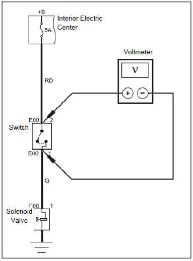
Voltage Drop Test
Hint:
Voltage drop test is to check the voltage drop along the wire, the connector or the switch.
1. Connect the positive wire of the voltmeter with the end of the wire close to the battery (connector side or switch side).
2. Connect the negative wire of the voltmeter with the other end of the wire (the other side opposite to the connector side or switch side).
3. Disconnect or close the switch to allow the circuit to work.
4. The voltmeter will show the voltage difference between the two points.
5. If the voltage difference exceeds 0.1 V (the voltage difference of a 5V circuit should be less than 50mV), the circuit is at fault.
Check whether there is any loose, oxidized or corroded connecting circuit.
Полный мануал в