
Электронная система управления двигателем JAC
HFC1041P73K1C3V
2.7 CTI Engine
Component
The electronic components involved in this chapter mainly include sensor, actuator and ECU.
Below mainly introduce working principle, structure, circuit and related maintenance of all electronic
components.
Generally, there are 3 wires in basic circuit of sensor, namely power supply, signal and grounding.
Some sensors don’t need power supply, or build-in power supply in ECU, therefore there are only signal
and grounding two wires; if uses housing grounding, there may be one signal wire connecting ECU, thus
make circuit very simple; but circuit of some sensors are very complicated. Complicated degree of sensor circuit depends on sensor’s type and structure principle, sensors in engine electrical control system mainly have switch type, resistance type, pulse type, voltage type, and so on.
Switch type sensor is the most simple structure, generally has 2 connecting terminals, its circuit has
grounding type and power supply type, in which grounding type is one terminal of switch is grounding
pin, one terminal of power supply type circuit is connected to power supply.
Resistance type sensor is mostly applied in electrical control system. Its structure has resistance variable type, potentiometer type, and so on; generally produces signal by the principle of direct circuit distributing voltage, and to ensure signal precision, ECU supplies a constant basic voltage as working voltage (generally is 5V).
Resistance variable type sensor has 2 connecting terminals, generally applies grounding type circuit, one terminal is signal, the other is grounding; potentiometer type sensor has 3 connecting terminals, namely power supply, signal and grounding.
Pulse type sensor has different principle and structure type, such as electromagnetic type using
electromagnetic induction principle, photoelectricity type using photoelectricity principle, hall type using hall effect, magnetic resistance type using magnetic resistance principle, and so on; and its circuit is fairly complicated.
Voltage type sensor generally uses electrochemistry principle and piezoelectric effect to transform change of detected data into change of voltage. Most voltage type sensors don’t need working power supply.
Actuators of electrical control system mainly have electromagnetic valve, electrical power motor, relay, triode switch circuit, indicating light, and so on. Actuator circuit generally is very simple, generally only has power supply and grounding two wires. ECU uses grounding control method to most actuators, power supply of these actuators comes from battery, and grounding wire is connected to ECU.
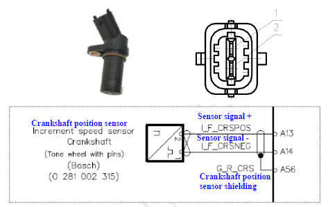
Crankshaft Position Sensor
1、Summary
Crankshaft position sensor is magnetoelectricity type sensor; piston position in burnt chamber decides starting time of fuel injection, engine piston connects to crankshaft by connecting rod, crankshaft position sensor can supply all data of piston position, and engine speed ensure crankshaft round per minute.
2、Working Principle
Crankshaft is connected to a ferromagnetic trigger wheel with 60 gears. There are 2 gears missing in actual used trigger wheel, which corresponding to some specified crankshaft position of 1st cylinder.
Crankshaft position sensor records gear sequence of trigger gear, and it consists of permanent magnet
and soft iron core with copper coil. Magnetic flux in sensor changes along with passed gear and
clearance, produce sine AC voltage, and its amplitude increases rapidly along with engine (crankshaft)
engine, and it also can achieve adequate amplitude even though engine speed is 50 r/min.
3、Installation Position
Crankshaft position sensor is installed in exhausting side of engine, and in front part of crankshaft.
4、Technical Parameter and Terminal Definition
Wiring terminal:
1—Crankshaft position sensor signal terminal
2—Crankshaft position sensor grounding terminal
Resistance: 860Ω;
Clearance between sensor and signal gear top : 0.5~1.5mm.
Temperature range:
Storage temperature: -20~50℃;
Working temperature: -40~120℃.
5、Installation Note
Sensor can only be opened before assembly;
Installing sensor must be pressed to install (It’s forbidden to knock);
Installation bolt tighten torque: 8±2 N.m;
6、Fault Phenomenon and Judging Method
General Fault Reason:
① Sensor inner component is damaged or inner circuit open circuit, short circuit, can’t produce signal;
② External circuit of sensor open circuit or short circuit;
③ Installation position of sensor is not right, clearance between rotor is too large, causing output signal abnormal;
Fault Phenomenon: power not enough, can’t start;
Detect Method:
1)Appearance Check
Check whether sensor installation is well, wiring harness connector is connected well and firmly;
check whether distance of hall component and signal wheel accord with standard requirement, and there
is no dirt or iron scurf between them; if any, please clear.
2)Resistance Measurement
Check sensor resistance, if resistance is too large or too small, sensor is damaged.
3)Circuit Detect
① Turn off ignition switch, and measure connecting condition of all wiring harness connectors;
② Measure resistance between ECU control wiring harness and connector, resistance is less than 3Ω;
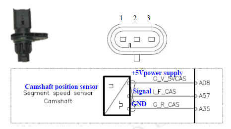
Camshaft Position Sensor
1、Summary
Camshaft position sensor can timely and truely induces relative rotating angle position of engine camshaft during engine running, supplies electrical signal to engine electronic control module (ECU), so that ECU rightly judges working phase position of engine each cylinder at the moment according to camshaft position signal inputed by camshaft position sensor, and make system control fuel injection and ignition sequence according to specified engine working sequence, thus to more accurately control engine combustion procedure and reduce harmful combustion emissions. Applicance of camshaft position sensor is useful to realize optimum control of engine each cylinder ignition and fuel injection timing.

2、Working Principle
Camshaft position sensor is hall-type sensor, which uses Hall effect to ensure position of camshaft, trigger wheel of one ferromagnet rotates along with camshaft, integrated circuit of Hall effect is installed between
trigger wheel and permanent magnet, and permanent magnet produces magnetic field which perpendicular to Hall-component. If one of the trigger wheels getting through streamlined sensor component (semiconductor chip), it changes intensity of magnetic field of perpendicular Hall-component, which will cause driving electron in long axis direction voltage deviate to direction that perpendicular to current, and produces instant signal voltage (Hall-voltage), and calculating circuit integrated with sensor Hall integrated circuit handle the signal and output with square wave signal.
3、Installation Position
Camshaft position sensor is installed in intake side of cylinder cover and below high pressure fuel rail.
4、Technical Parameter and Terminal Definition
Working voltage: 5V
Signal gear addendum sensor output voltage: +0.5V
Signal gear dedendum sensor output voltage: -0.5V
Wiring terminal:
1— +5V power supply
2—Signal output
3—Grounding
Clearance between sensor induction terminal and camshaft signal wheel is: 0.35~1.65mm.
5、Installation Note
Sensor surface is clean, and there is no crack;
Tighten torque of sensor installation bolt: 10±2 N.m.
6、Fault Phenomenon and Judging Method
General Fault Reason:
① Sensor inner component is damaged, or inner circuit is open circuit, short circuit, can’t produce signal;
② Sensor outer circuit is open circuit or short circuit;
③ Installation position of sensor is not right, clearance with rotor is too large, causing output signal abnormal.
Fault Phenomenon:
If camshaft position sensor input signal is wrong, it can’t inject fuel in order, which is easy to cause
engine misfire, idling unsteadily, accelerating weakly, and so on.
Detect Method:
Appearance Check
Check whether installation of sensor is firmly, wiring harness connector is connected well and firmly, distance between Hall-component and signal wheel is accord with requirement, there is dust or iron scurf; if any, please clear.
Circuit Check
Hall sensor can produce signal only in the condition of power supply grounding is normal, thus first check its power supply circuit and grounding circuit.
① Close ignition switch, and disconnect wiring harness connector of sensor.
② Open ignition switch, use multimeter to respectively measure all terminals of sensor wiring harness connector.
Measure sensor power supply terminal, it should be 4.5~5V reference voltage. If voltage value is not accord with, it indicates there is fault in control circuit or ECU, and should detect further.
Measure sensor grounding terminal, and resistance between it and battery negative electrode should be less than 3Ω; if abnormal, should maintain grounding circuit.
③ If check above is abnormal, close ignition switch, disconnect ECU wiring harness connector, and check whether there is open circuit or short circuit between sensor connecting terminal and ECU connecting terminal.
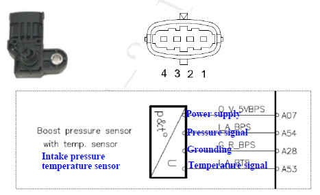
Intake Pressure Temperature Sensor
1、Summary
Intake pressure temperature sensor characterizes engine actual intake state when engine running, thus it is one of the main components of characterizing engine running working condition and load state.
2、Working Principle
Intake pressure temperature sensor integrates the function of pressure sensor and temperature sensor.
Pressure sensor part (MAP) is designed by principle of piezoelectricity technical, when induced pressure, it produces output signal which is proportional to input pressure. Pressure level directly indicates engine current load and working state. It has conclusive effect to engine management system output control state.
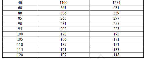
Core temperature sensor component of temperature sensor consists of semiconductor thermal resistor of negative temperature coefficient. Its temperature characteristic is negative temperature coefficient (NTC) thermal resistor, when temperature increases, output resistance value of thermal resistor decreases; when temperature decreases, resistance value of thermal resistor increases.
ECU supplies 5V direct current signal for engine intake temperature sensor and measure its voltage drop according to itself circuit, and engine management system will judge engine actual working tate according to the voltage signal.
3、Installation Position
Intake pressure temperature sensor is installed intake manifold, and pressure measurement function is prior.
4、Technical Parameter and Pin Definition
Working voltage: +5V
Working temperature: -40~130℃
Pressure measuring range: 50~400Kpa, highest is 600Kpa
Pressure measuring response time: <1.8ms
Temperature measuring response time: ≤10s

Pin definition:
1—Grounding
2—Temperature signal
3—Power supply +5V
4—Pressure signal
5、Installation Note
When installing, ensure pressure port faces downward, and angle between it and vertical direction is less than 60°;
Installation bolt tighten torque: 6±2 N.m;
6、Fault Phenomenon and Judging Method
General fault reason: sensor inner circuit open circuit, or dirt piled up, intake pipe leaking causes signal incorrect.
Fault phenomenon: when fault appears, it will cause fuel injection function of engine ECU abnormal, and appears the phenomenon of mixed gas too dense or too thin, engine abnormal idling running or bad accelerating, exhausting pipe giving off black smoke, and so on.
Maintenance Note: it’s forbidden to disassemble sensor.
Detect Method:
1)Appearance Check
Check whether sensor wiring harness connector is connected well and firmly. Check whether sensor installation is loosen or dropped. Check whether extrinsic feature is good, and ensure there is no knock mark. Check whether sensor check hole is blocked.
2)Circuit Check
① Turn off ignition switch, disconnect sensor wiring harness connector;
② Turn on ignition switch, use multimeter to respectively measure all terminals of sensor wiring harness connector;
a、Measure power supply terminal of sensor, and it should be 5V reference voltage. If voltage value is not accord with, it indicates there is fault in control circuit or ECU, and check further.
b、Measure sensor grounding terminal, and resistance between it and battery negative electrode should be less than 3Ω; if abnormal, should maintain grounding circuit.
If check above is abnormal, turn off ignition switch, disconnect wiring harness ECU connector, and check whether there is phenomenon of open circuit or short circuit in wiring harness between sensor connector and ECU connector.