
Shacman X3000 Электрические схемы
Content
- Part 1: Power
- Part 2: Combination meter
- Part 3: LightingSystem
- Low beams
- High beams
- Position Lights
- Turn signals
- Fog Lights
- Auxiliary high beams
- Brake lights
- Reversing Lights
- Indoor Lights
- Task Lights
- Cigarette lighter
- SECTION 4: CAB APPLIANCES
- Wipers and sprays
- Horns
- DoorControlSystem
- SECTION 5:HEATING AND AIR CONDITIONING SYSTEMS
- Part VI:Multimedia Systems
- Part VII:Chassis Appliances
- Inter-wheel and inter-axle differential locks
- Power take-off
- Tipping back
- SECTION VIII: POWERTRAIN
- Part IX: Reserved Interfaces
- Part 10: Bus Topology
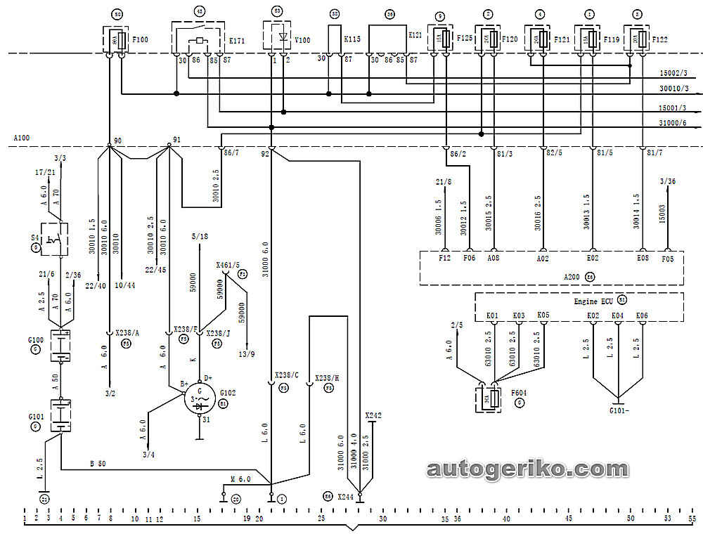
A100 Central electrical installation board
A200 Central Body Controller
F100 Loadfuse
F119 CBCUpowersupply3fuse
F120 CBCUpowersupply5fuse
F121 CBCUpowersupply6fuse
F122 CBCUpowersupply4fuse
F604 Engine ECU fuse
G100 Battery I (135/180Ah)
G101 Battery 2 (135/180Ah)
G102 Generator (70A/80A)
K171 load relay
S4 Mechanical main power switch
V100 Load anti-interference diode
K115 The 38th positionconnectingpieceof the central electricalboar
K121 The 38th positionconnectingpieceof the central electricalboar
X238 35-hole connector (cab-engine, transmission)
X242 Cab left ground point
X244 Cab right ground point
X461 8-hole connector (reserved signal)
For conductors with unmarked cross-sectional area, the cross-sectional area is 1mm2.
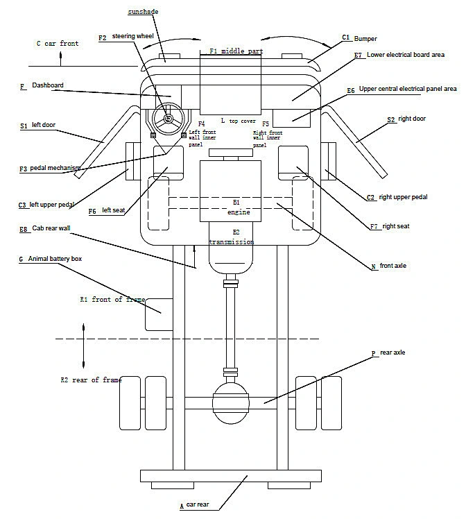
Location name Code
car rear A
Engine B1
Transmission B2
car front C
Bumper C1
Upper right pedal C2
Left upper pedal C3
Sunshade C4
Upper central electrical panel area E6
Lower central electrical panel area E7
Cab rear wall E8
Dashboard F
Middle section F1
Steering wheel F2
Pedal mechanism F3
Left front wall inner panel F4
Right front wall inner panel F5
Left seat F6
Right seat F7
Battery box G
Top cover L
Front axle N
rear axle P
Frame front R1
Rear of frame R2
Left door S1
Right door
Все схемы в высоком качестве в