
CASE CX130
(диагностика, схемы, ремонт)
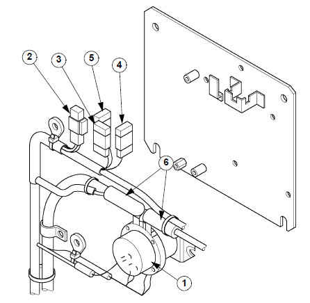
General location of components (outside the cab)
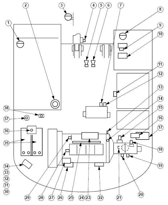
2. Rotary light
3. Attachment working light
4. Overload indicator pressure detector
5. Horn (low note)
6. Horn (high note)
7. Pilot pressure switch (yellow ring)
8. Working light (upperstructure)
9. Windshield washer motor
10. Fuel filler pump
11. Fuel level indicator
12. Travel pilot pressure switch
13. Engine speed detector
14. Engine oil pressure
15. Proportioning valve
16. Engine emergency stop motor
17. 6 solenoid valve block
18. Hydraulic pump regulating pressure detector
19. P2 pressure detector (yellow ring)
20. P1 pressure detector
21. Hydraulic oil temperature sender
22. Starter motor
23. Electronic regulator
24. Fuel flow regulating resistor
25. Pre-heater plugs
26. Air conditioning compressor magnetic clutch
27. Alternator
28. Engine water temperature sender
29. Fuel temperature sender
30. Battery relay
31. Main protective fuse for circuits F11 and F12
32. Main protective fuse for circuits F3 to F10 and F13 to F20
33. Main protective fuse for circuit F2
34. Main protective fuse for circuit F1
35. Batteries
36. Coolant solution level
37. Air conditioning compressor magnetic clutch contact switch
38. Swing pilot pressure switch
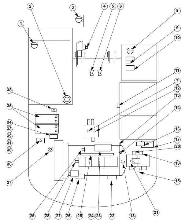
1. Working light (cab)
2. Rotary light
3. Attachment working light
4. Overload indicator pressure detector
5. Horn (low note)
6. Horn (high note)
7. Pilot pressure switch (yellow ring)
8. Working light (upperstructure)
9. Windshield washer motor
10. Fuel filler pump
11. Fuel level detector
12. Travel pilot pressure switch
13. Engine speed detector
14. Engine oil pressure
15. Proportioning valve
16. Engine emergency stop motor
17. 6 control valves block
18. Hydraulic pump regulating pressure detector
19. P2 pressure detector (yellow ring)
20. P1 pressure detector
21. Hydraulic oil temperature sender
22. Starter motor
23. Electronic regulator
24. Fuel flow regulating resistor
25. Pre-heater plug
26. Air conditioning compressor magnetic clutch
27. Alternator
28. Engine water temperature detector
29. Fuel temperature detector
30. Battery relay
31. Main protective fuse for circuits F11 and F12
32. Main protective fuse for circuits F3 to F10 and F13 to F20
33. Main protective fuse for circuit F2
34. Main protective fuse for circuit F1
35. Batteries
36. Coolant solution level
37. Air conditioning compressor magnetic clutch contact switch
38. Swing pilot pressure
Relays and main fuses (battery compartment)
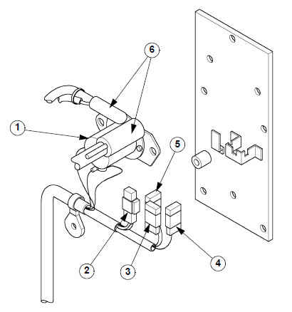
1. Battery relay
2. Fuse 65A: protection of circuits F3 to F10 and F13 to F20A
3. Fuse 20A: protection of circuits F11 and F12 (before contact)
4. Fuse 20A: protection of circuits F1
5. Fuse 20A: protection of circuits F2
6. Battery cables
General location of components (inside the cab)
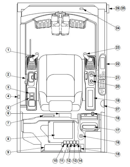
1. Horn switch
2. Controls cancellation lever contact switch
3. Switch for hammer/grab
4. Door contact switch
5. Overload indicator switch
6. Air conditioner
7. Fuse box
8. Main electronic control box
9. Engine electronic control box
10. Rotary light relay
11. Engine emergency stop relay
12. Working lights relay
13. Horn relay
14. Pre-heat plug relay
15. DC-DC converter (24 V - 12 V)
16. Solar radiation detector
17. Radio
18. Cigarette lighter
19. Air conditioning control
20. Starting contact switch
21. Throttle control
22. Instrument panel
23. Engine idle control
24. Windshield contact switch
25. Windshield wiper motor electronic control box
26. Windshield wiper motor
27. Cab interior lighting
Fuse box
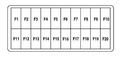
F1 Fuse 20A: Engine electronic control box
F2 Fuse 20A: Electronic box control
F3 Fuse 20A: Power for electronic control box
F4 Fuse 10A: Hydraulic control cancellation
F5 Fuse 15A: Grease fitting (not used)
F6 Fuse 10A: Rotary light
F7 Fuse 20A: Fuel filler pump
F8 Fuse 15A: Engine emergency stop motor
F9 Fuse 30A: Pre-heater plug
F10 Fuse 10A: Option
F11 Fuse 10A: Memory
F12 Fuse 10A: Starting, radio and cab light switch
F13 Fuse 20A: Air conditioning, heating
F14 Fuse 5A: Air conditioning compressor
F15 Fuse 15A: Working lights
F16 Fuse 15A: Working light (not used)
F17 Fuse 10A: DC converter (24 V - 12 V)
F18 Fuse 15A: Windshield wiper and washer
F19 Fuse 10A: Horn
F20 Fuse 15A: Cigar lighter and cab seat
Instrument panel
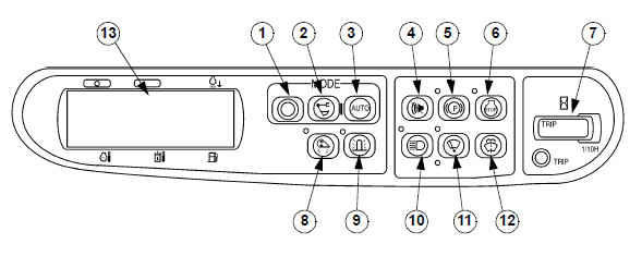
1. Travel mode switch
2. Working mode switch
3. Automatic mode switch
4. Buzzer stop switch
5. Swing brake switch
6. Engine emergency stop switch
7. Hourmeter
8. Shock absorption (Hard/soft) switch
9. Rotary light switch
10. Working light switch
11. Windshield wiper switch
12. Windshield washer switch
13. Control screen
BASIC OPERATING PRINCIPLES
Engine control
1) Circuit configuration
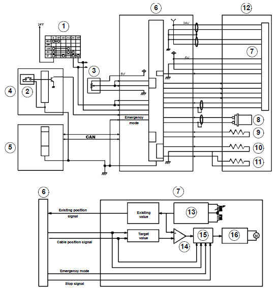
1. Starter motor switch
2. Emergency stop switch
3. Throttle control
4. Instrument panel
5. Main electronic control box
6. Engine electronic control box
7. Electronic acceleration
8. Engine speed detector
9. Fuel flow regulating resistor
10. Engine water temperature sender
11. Fuel temperature sender
12. Engine
13. Rack detector
14. Control circuit
15. Cancellation circuit
16. Electronic acceleration circuit
2) Fuel consumption control
1. The engine electronic control box (6) calculates the target speed based on:
- working mode data sent via CAN communications from the main electronic control box (5),
- voltage signals from the acceleration control (3),
- voltage signals from the water temperature sender (10),
- voltage signals (starter motor switch 1) which feed the engine electronic control box.
2. The engine electronic control box calculates the fuel flow from the difference between the target speed (electronic acceleration tachometric sender) and the real speed (engine speed detector 8), 3. The engine electronic control box converts the fuel flow at the target position of the electronic acceleration rack (7) and corrects that target position in accordance with the regulating resistance (9).
3) Engine starting control
1. When the contact switch (1) is in the starting position the starting signal is sent simultaneously to the starter motor and the engine electronic control box.
2. The engine electronic control box determines the fuel injection flow. This flow is determined from the water temperature data and the real number of revolutions of the engine.
3. Once the starting signal is extinguished, the engine electronic control box changes from starting fuel control to normal fuel injection flow control.
4) Engine stop control
When the engine stop signal is received (when the ignition switch is turned off or the emergency stop control is (2) is operated), the engine electronic control box transmits the rack position signal "no injection" to the electronic acceleration and activates the engine stop signal.
5) Electronic acceleration assistance error and emergency mode
1. The rack detector signal reaches the engine electronic control box.
2. The engine electronic control box compares the target position and the real position of the rack.
3. If the engine electronic control box determines that the rack is not in the correct target position, it will consider it to be an assistance error and will stop the engine.
4. If the emergency mode is activated when an electronic acceleration assistance error occurs, the engine operates in emergency mode (See "Emergency Mode" Section).
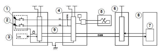
Working mode selection
1) Circuit configuration
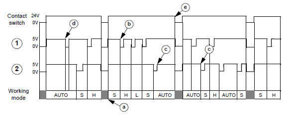
2) Timing diagram
1. Working mode switch
2. Automatic mode switch
3. Instrument panel
4. Main electronic control box
5. Proportioning valve
6. Engine electronic control box
7. Electronic acceleration
8. Engine
9. SERIES communication
3) Mode selector switch
a) When the ignition is switched on, "S" is selected by default (unless auto mode auto was selected when the ignition was switched off)
b) Every time the travel mode switch (1) is pressed, the mode changes:
S -> H -> L -> S -> H
c) If the auto mode switch (2) is operated, the mode changes to auto mode. If the auto mode switch is pressed again, the mode changes to "S" mode.
d) When auto mode is running, if the work mode switch (1) is pressed, the mode does not change.
e) If the ignition is switched off in auto mode, the mode stays in auto when the ignition is switched on again.
4) Operation
1. The mode switch signal (1 and 2) is managed by the main electronic control box (4) which changes the mode in accordance with the input signal.
2. The electronic control box (4) transmits the selected mode to the control screen (LCD) via series communications (9). The control screen shows the mode selected.
3. The main electronic control box (4) transmits the selected mode to the engine electronic control box (6) via CAN communications which controls the electronic acceleration (7).
The engine electronic control box (6) transmits the mode and the data concerning the number of revolutions to the main electronic control box (4) via CAN communications.
4. The main electronic control box (4) calculates the proportioning valve current (5) based on the mode selected and the data concerning the real number of revolutions of the engine and the target number of revolutions.
5. The main electronic control box (4) transmits the new data to the display screen (LCD) via series communications.
Полный мануал в