
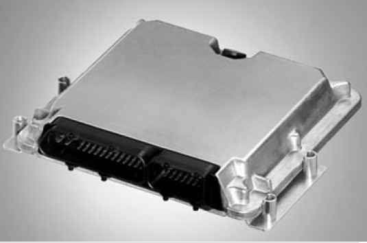
ECU Rexroth BODAS Controller RC Series 20
Contents
- Ordering code
- Description
- Block circuit diagram
- Technical data
- Connection diagram RC2-2
- Connection diagram RC4-4
- Connection diagram RC6-9
- Connection diagram RC12-18
- Overview of functions
- Dimensions RC2-2
- Dimensions RC4-4, RC6-9
- Dimensions RC12-18
- Installation position
- Mating connector
- Safety instructions
Features
–– Component of BODAS system for mobile applications
–– Robust design meeting specifications for mobile applications
–– High electromagnetic compatibility (EMC)
–– Inputs and outputs with fault detection
–– Safety features such as redundant inputs and central safety cut-off for all outputs
–– Pulse-width-modulated (PWM) solenoid currents for minimum hysteresis
–– Closed-loop control of solenoid currents, i.e. not dependent on voltage and temperature
–– Sturdy, sealed aluminum housing
Main components
–– Powerful 16-bit microcontroller module
–– Protected watchdog for program run monitoring
–– Serial data interface and CAN-bus interface for diagnostics, parameter setting and display of process variables
–– Supply voltage and ground connections for potentiometers and sensors

Note:
The BODAS controllers are not functional without software.
In order to use the BODAS controllers, you also need:
– BODAS standard software or
– Application-specific software
Optional accessories:
––BODAS-design software
The Windows-based PC software BODAS-design (RE 95112) is used for programming the BODAS controller RC. All graphic and text-based programming languages specified in the IEC 61131-3 standard are available for programming.
––BODAS-service software
The Windows-based PC software BODAS-service (RE 95086) is used for displaying functions, errors and system variables as well as for setting parameters via a PC.
––BODAS measuring adapter MA
The BODAS measuring adapter MA (RE 95090) is used for measuring all electric signals at the inputs, outputs and interfaces of the BODAS controller. For test purposes, it is connected in series between the controller and the vehicle or device wiring.
––BODAS test box TB3
The BODAS test box TB3 (RE 95092) is used for simulating vehicle and equipment functions for development and test purposes with BODAS controllers. The BODAS test box TB3 is connected to the controller with the adapter cable TAK1/10.
––BODAS CAN I/O extension module RCE12-4/22
The BODAS CAN I/O extension module RCE12-4/22 (RE 95220) is used for I/O extension of a controller in the event that the number of controller inputs and outputs is insufficient for the specified application.
All products mentioned here are available from Bosch Rexroth.
Further information can be found on the Internet at:
RC / 20
01 02 03
Ordering code Description
The BODAS controllers RC are used for the programmable control of proportional solenoids and additional switching functions.
They can therefore be used for both simple and complex open- or closed-loop controls, e.g. for hydrostatic travel drives, working hydraulics or transmission control in mobile working machines.
BODAS controllers RC were specially developed for use in mobile working machines, and satisfy the relevant safety requirements with regard to ambient temperature, tightness, resistance to shock and vibration, as well as electromagnetic compatibility (EMC). Internally, BODAS controller RC consist of a powerful 16-bit microcontroller and all input and output circuitry.
Analog voltages, resistances frequencies and switching information are processed as input signals. The inputs are protected against overvoltage and electrical interference. The voltage inputs can be monitored to detect any cable breaks or short circuits.
The proportional solenoid outputs are pulse-width-modulated (PWM) and optimally adapted for electric proportional control of axial piston units and valves to ensure high accuracy and minimum hysteresis.
The switched outputs are designed for the direct switching of relays, lamps and switching solenoids.
The RS232 serial interface enables the connection of a laptop to the BODAS-service PC software for service functions, such as diagnostics, parameter setting or display of process variables.
CAN-bus interfaces are available with all BODAS controller RC for exchanging data with other bus users or electronic systems (e.g. RC or RCE, joystick valves, diesel engine injection, display). The CAN-bus interfaces can each be operated with different protocols.
BODAS standard programs are available for the BODAS controller RC software. If more extensive functions are required, special program packages for specific applications can also be compiled using a program library and adapted to the application in question with the aid of service tools. Programming with BODAS-design is also possible.
Combined with pumps, motors, valves, sensors, input devices and actuators from Bosch Rexroth, BODAS controllers RC and corresponding software can be used to create complete system solutions.
Block circuit diagram
Controller
Note:
The block circuit diagram applies for controllers RC2-2/20, RC4-4/20, RC6-9/20.
For controller RC12-18/20, the respective block circuit diagrams for the master and slave apply.

1) The inputs and outputs are partially mutually isolated by the technical circuitry.
2) In the RC2-2/20 only
3) Not in the RC2-2/20
Connection diagram RC2-2
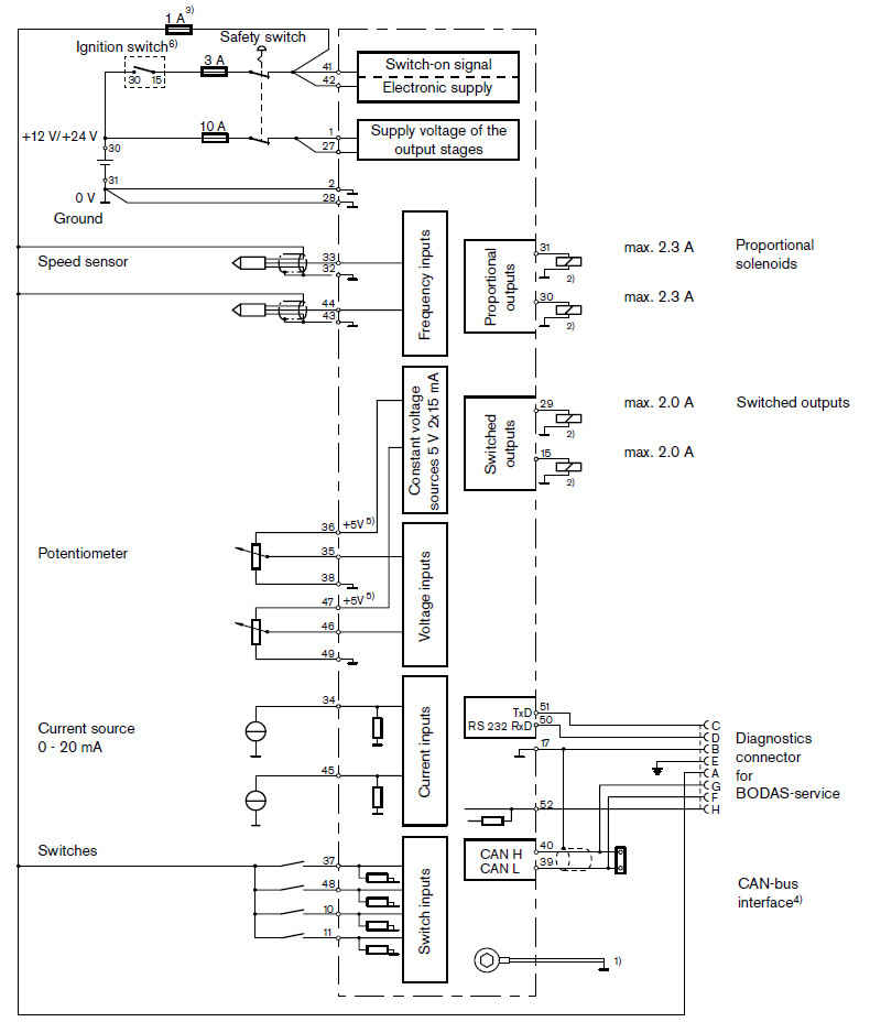
1) Short, low-resistance connection from a case screw to the device ground or vehicle ground
2) Separate ground connection from solenoid return line to battery (chassis possible)
3) Separate fuses for switches and sensors necessary
4) CAN bus: termination resistor 2 x 120 Ω necessary
5) Alternatively, 5 V/ground outputs may also be used to supply the sensors
6) The terminals are labeled according to DIN 72 552. This does not apply for the controller.
Connection diagram RC4-4
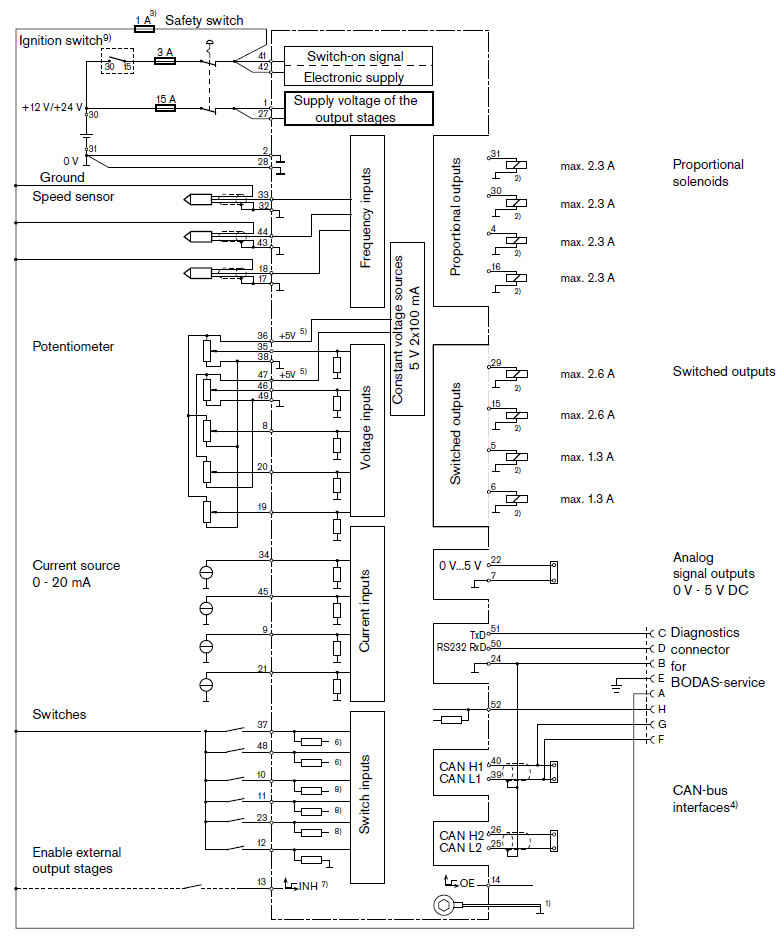
1) Short, low-resistance connection from a case screw to the device ground or vehicle ground
2) Separate ground connection from solenoid return line to battery (chassis possible)
3) Separate fuses for switches and sensors necessary
4) CAN bus: termination resistor 2 x 120 Ω necessary
5) Alternatively, 5 V/ground outputs may also be used to supply the sensors
6) Can be switched together between high/low active by means of software
7) Enable the output stage level ≥ 5 V (proportional and switched outputs)
8) Switched together between high/low active by means of software
9) The terminals are labeled according to DIN 72 552. This does not apply for the controller.
Connection diagram RC6-9
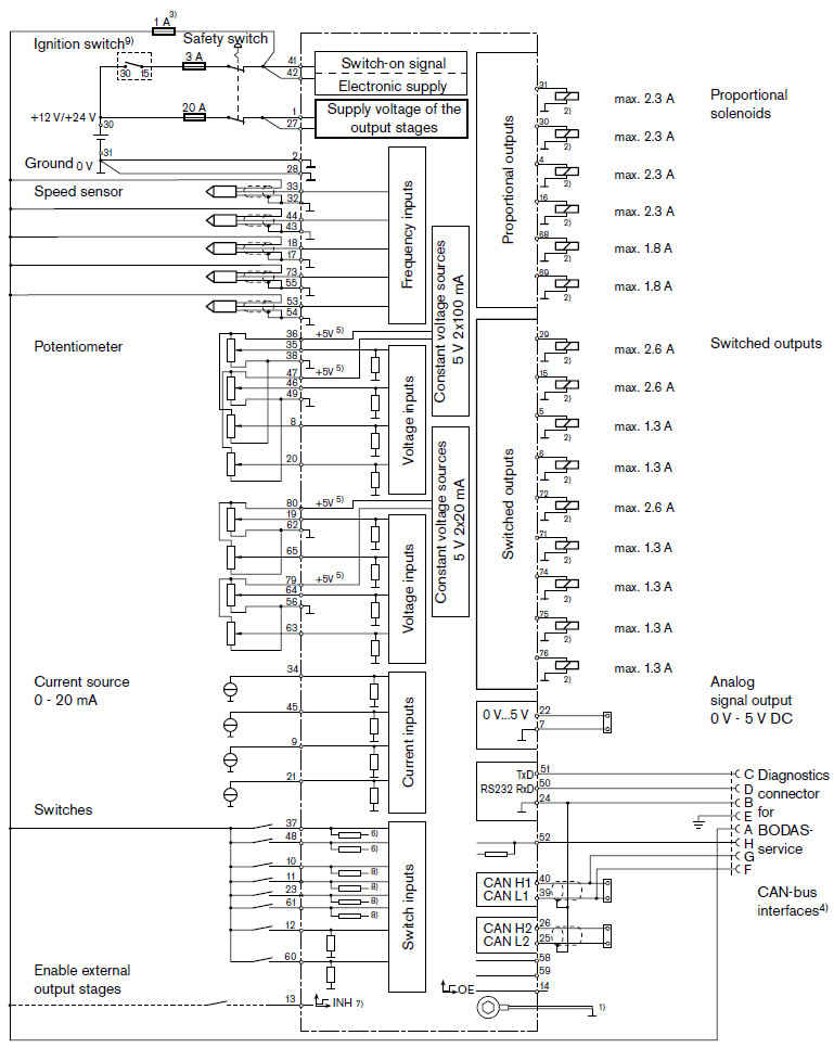
1) Short, low-resistance connection from a case screw to the device ground or vehicle ground
2) Separate ground connection from solenoid return line to battery (chassis possible)
3) Separate fuses for switches and sensors necessary
4) CAN bus: termination resistor 2 x 120 Ω necessary
5) Alternatively, 5 V/ground outputs may also be used to supply the sensors
6) Can be switched together between high/low active by means of software
7) Enable the output stage level ≥ 5 V (proportional and switched outputs)
8) Can be switched together between high/low active by means of software
9) The terminals are labeled according to DIN 72 552. This does not apply for the controller.
Connection diagram RC12-18
The connection of Master A and Slave B for the RC12-18/20 is to be performed as shown below.
All Master A and Slave B inputs and outputs that are not shown are identical in terms of function and specification to those of the RC6-9/20.
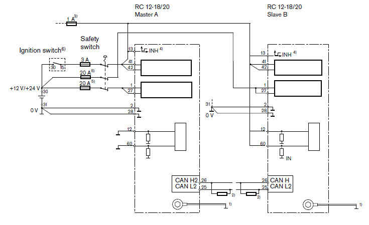
1) Short, low-resistance connection from a case screw to the device ground or vehicle ground
2) CAN bus: termination resistor 120 Ω necessary (see installation instructions RDE 90 300-01)
3) Supply voltage for external sensors and switches
4) Master A and Slave B interlock of the outputs by "cross" wiring terminals 13 and 14 at both controller units
5) The fuses function as line protection. The design is performed by the machine manufacturer.
6) The terminals are labeled according to DIN 72 552. This does not apply for the controller.
Connection variants
Monitored potentiometer 1 to 5 kΩ
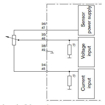
7) Internal pull-down resistor
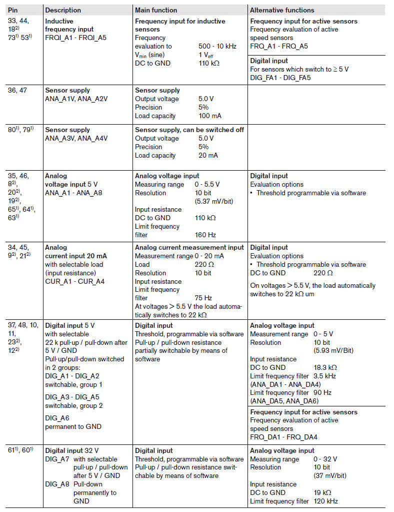
Overview of functions
Продолжение и весь мануал в