
FORD CARGO H566/H476 - EBS и распиновки
EBS
Main Functions:
Functions of EBS system are applied in the central control unit (ECU). Some functions are optional and may be activated or deactivated by EoL programming. Some EBS functions are as follows.
Brake power control
Driver’s speed reduction demand is recorded and according to this demanded speed reduction, brake pedal position characteristic is converted to braking pressures considering the axle load independently of the load condition of the vehicle. Brake pedal characteristics may be set by EoL parameter.
ABS function.
The purpose of ABS function is to prevent locking of wheels during braking in order to maintain steerability and stability of the vehicle and minimize the stop distance. ABS intervenes braking at every condition where the friction available between the road and the tire of a wheel is lower than the braking power applied to the wheel and thus it causes that the wheel reduces speed very quickly (wheel locking).
Automatic Traction Control function
The purpose of ATC (Automatic Traction Control) function is to maintain the stability of vehicle while driving and prevent slippage of the driven wheels in order to increase traction power during acceleration. ATC may be divided to two sub-functions: engine control and brake control.
DTC function
The purpose of DTC (Direct Torque Control) is to prevent the inclination of driven wheels to lock caused by the engine inertia on a low friction surface. If the average speed of driven wheels indicate a locking due to low friction, DTC demands a specific amount of engine torque to drive the driven wheels.
Brake assist function
As per the experiences, pedal movement of the driver is adequately quick on the start of an emergency braking only and it is not possible to apply the brakes fully. The purpose of this function is to assist the driver in such a condition and provide him a precious time in the first, quick operation of the emergency braking. Brake pressure shall be increased compared to the real demand of the driver according to the brake demand and movement speed of brake pedal.
Retarder integration
The purpose of this function is to reduce the friction brakes by using auxiliary brakes instead of braking power. Auxiliary brakes (engine controlled resistance brake and primary or secondary retarder) are automatically applied by EBS when brake pedal is pressed. Retarder integration function does not change the conformity of towing and towed vehicles (retarder assists braking of both towing and towed vehicles).
Connection power control
The purpose of the Connection Power Control function is distributing the brake energy between towing and towed vehicle. The output of the function is a differential pressure that changes the trailer connection head pressure.
Trailer brake function
Trailer brake function allows braking of the trailer independently of the vehicle. Using a button in the instrument cluster, EBS sets 4 bar pressure to trailer if the vehicle speed is under a specified limit (almost stationary).
Differential lock prevention
Power supply to differential lock switch shall be coming from EBS. EBS checks the speed difference between drive wheels and if the speed difference is over a limit, it prevents the activation request to prevent damage to the differential lock.
Hill Start Assist function
Hill Start Assist function is used for assisting the uphill starts by maintaining the service brake pressure or delaying the release of service brake in order to provide Violete time for the driver as he switches through the pedals. This function is not intended to be used as park brake.
ESP Function
ESP (Electronic Stability Program) is intended to maintain the drive stability of the vehicle. This can only be achieved within rules of physics! ESP consists of two sub-functions.
Yaw Control (YC): intended for conditions such as sharp turns in low and medium-μ conditions, low and excessive steering etc.
Roll-Over Protection (ROP): reduces the risk of roll-over in high and medium-μ conditions.
Driver information and troubleshooting
Warning and information screens are different for different applications; and these are connected to
electrical system of the vehicle. EBS5’s basic communication interface for display and warnings is the CANJ1939
communication line (KWP over CAN), which is also the interface for troubleshooting. However, some lamps may be
directly controlled from EBS ECU.
EBS System Components:
1- Foot Brake Module (FBM)
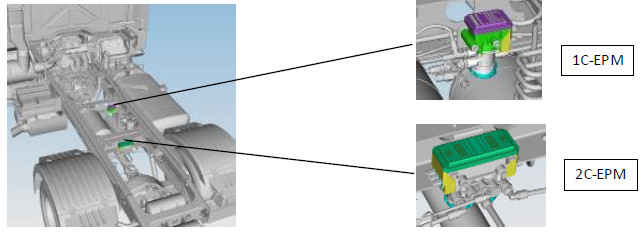
2- Electro-Pneumatic Valve (EPM)
2.1- 1C-EPM (1 Pressure Channel)
2.2- 2C-EPM (2 Pressure Channels)
3- Trailer Control Valve (TCM)
4- Pressure Control Valve (PCV)
5- Axle Load Sensor (ALS)
6- Steering Angle Sensor (SAS)
7- Yaw Rate Sensor (YRS)
8- EBS Control Unit (EBS ECU)
9- Wheel Speed Sensor (WSS)
Foot Brake Module (FBM)
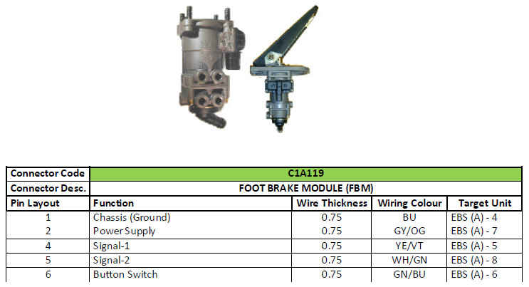
A displacement sensor integrated to foot brake module of the EBS system in order to measure the brake pedal movement that will be transferred to the driver’s speed reduction demand. FBM also includes two pneumatic
control circuits. In case of a serious electric fault in the system, vehicle may be braked with the pneumatic backup line.
Electro-Pneumatic Module (EPM)
EPM is an electro-pneumatic control. It consists of a relay valve, filter, muffler, solenoid valve for backup circuit, an input and output valve (solenoids), pressure sensor, electronic control unit and pneumatic and electronic connections. Wheel speed sensors and lining wear sensors may also be connected to EPM that shall transfer the signal to EBS-ECU via Brake-CAN.
There are two types of EPM available:
- 1C-EPM: this is a single channel control. It can serve a pneumatic channel with two wheels. It is used for the front axle of the vehicle.
- 2C-EPM: this is a dual channel control. It may serve two individual pneumatic channels with four wheels. It is used for the rear axle of the vehicle.

Trailer Control Module (TCM)

TCM is an electro-pneumatic control designed for trailer pressure control. It consists of a relay valve, filter, muffler, solenoid valves for backup circuit, an input and output valve (solenoids), pressure sensor and pneumatic and electronic connections. Also, brake pressure is controlled by the park brake system beside the service brake system.
Pressure control valve (PCV)

As single channel EPM is used on front axle, a pressure control valve is also used. Pressure control valves are required for ESP and improved ABS functions. There is one valve each on front right and front left wheels.
Axle Load Sensor (ALS)
Axle load sensor is a pressure sensor that generates analog output voltage in technical terms. It is placed on the rear suspension bellow and informs the EBS system by generating a signal proportional to the bellow pressure.
ECU uses the axle load information in critical setting such as braking power.
Electrical connection of the load sensor is with 2C-EPM. It takes the 5V power supply from 2C-EPM.

Steering Angle Sensor (SAS)
Steering angle sensor (SAS) is a no-contact, analog angle sensor that measures the absolute angle position of the steering wheel. It outputs a digital sensor value via CAN interface. This sensor is required for EBS with ESP.
Sensor is installed to the steering shaft so that it shall measure the rotating angle of the steering wheel only without any intervention from any additional secondary motions.
When the sensor is replaced, it shall be calibrated with the FODP2 software.

EBS Wiring Diagram
