
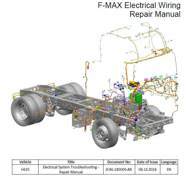
FORD F MAX H625 Руководство по ремонту электропроводки
Charts and Diagrams Referenced In This Manual:
Item No. Name of the wiring Middle No. 2D Diagrams
1
Driver side cab internal wiring
14A005
JC46-14A005-ABB
2
BCU wiring (Main wiring)
14398
JC46-14398-MFB
3
Door internal wiring - Left
14A584
JC46-14A584-AAB
4
Cab internal wiring from driver side to passenger side
14B242
JC46-14B242-AAB
5
Driver side cab internal rear wiring
14014
JC46-14014-ABB
6
Door internal wiring - Right
14K138
JC46-14K138-AAB
7
TPMS, Radar, OAT and Horn Wiring
13B767
JC46-13B767-DB
8
Passenger side cab internal wiring
13B712
JC46-13B712-AEB
9
Driver side roof wiring
15B594
JC46-15B594-AB
10
Bumper wiring
13N052
JC46-13N052-AB
11
Roof wiring
15A404
JC46-15A404-ADB
12
Cab lift, wet type webasto wiring
13B711
JC46-13B711-DB
13
On-transmission wiring
14K039
JC46-14K039-ABB
14
Transmission-cab wiring
15A808
JC46-15A808-RAB
15
Exhaust-SCR wiring
9L430
JC46-9L430-AB
16
cab internal console wiring
14401
JC46-14401-ASB
17
Console wiring attachment-1
14A320
JC46-14A320-BB
18
Console wiring attachment-2
19C603
JC46-19C603-AB
19
Sensor on engine wiring
12A690
JC46-12A690-AFB
20
Injector wiring
9H589
JC46-9H589-C
21
Passenger side Engine ground wiring
14303
JC46-14303-AB
22
ADR Wiring - 24V from the battery
14405
JC46-14405-MBB
23
Driver side cab internal ground wiring
14F416
JC46-14F416-AB
24
ADR Wiring
14N013
JC46-14N013-UA
25
Battery wiring
14304
JC46-14304-AB
26
ADR Wiring - 24V from the battery
14300
JC46-14300-UB
27
Alternator-mega fuse-battery wiring
14A280
JC46-14A280-UB
28
Switch-ground wiring
10K701
JC46-10K701-TB
29
Switch-battery-ground wiring
14301
JC46-14301-UB
30
Relay - air heater ground wiring
6B018
JC46-6B018-A
31
Alternator-start/stop-starter wiring
12A522
JC46-12A522-BB
32
Air heater ground wiring
6B019
JC46-6B019-BB
PREFACE
This repair manual is prepared for providing correct and appropriate workshops services in technical manner for Ford Cargo vehicles.
This manual covers the information and repair methods required for performing electrical repair work that will be carried on the vehicle. Described repairs shall be performed by qualified and trained personnel.
It covers information on the system description, operation, and displaying the system on the vehicle, and electrical circuit diagrams, connector positions and pin layouts. Also, safety rules are provided in the introduction section.
0.0.0.0: Description
1.0.0.0: Introduction
1.1.0.0: Safety Alert
1.2.0.0: Warnings
1.3.0.0: Workshop Equipment
2.0.0.0: Fuses and Relays
2.1.0.0: General Description for Fuses
2.2.0.0: Fuse and Relay Box
2.2.1.0: Fuses
2.2.2.0: Relays
2.3.0.0: Mega Fuse
3.0.0.0: Electric Wirings
3.1.0.0: Basic Approaches on Fault Finding
3.1.1.0: Electric Wiring Repair Methods
3.2.0.0: Wiring Diagram Abbreviations
3.3.0.0: Electric wiring on vehicle
3.3.1.0: 14A005:Driver side cab internal wiring
3.3.2.0: 14B242:Cab internal wiring from driver side to passenger side
3.3.3.0: 14014:Driver side cab internal rear wiring
3.3.4.0: 13B712:Passenger side cab internal wiring
3.3.5.0: 15B594:Driver side roof wiring
3.3.6.0: 15A404:Roof Wiring
3.3.7.0: 13B767:TPMS, Radar, OAT and Horn Wirings
3.3.8.0: 13N052:Bumber wiring
3.3.9.0: 13B711:Cab lift, wet type webasto wiring
3.3.10.0: 14401:Cab internal console wiring
3.3.11.0: 14A320: Console wiring attachment-1
3.3.12.0: 19C603: Console wiring attachment-2
3.3.13.0: 14A584:Door internal wiring - Left
3.3.14.0: 14K138:Door internal wiring - Right
3.3.15.0: 14398: BCU wiring (Main Wiring)
3.3.16.0: 14405:Rear Wiring
3.3.17.0: 12A690:Sensor on Engine Wiring
3.3.18.0: 9H589:Injector Wiring
3.3.19.0: 9L430 – 14D378:Exhaust-SCR Wiring
3.3.20.0: 14K039:On-transmission wiring
3.3.21.0: 15A808:Transmission-cab wiring
3.4.0.0: Chassis (Ground) Connections
3.4.1.0: Chassis (Ground) Connections Chart
3.4.2.0: 6B019:Air heater frame wiring (Ground)
3.4.3.0: 6B018 + Relay - Air heater ground wiring (Ground)
3.4.4.0: 14301:Switch-battery-frame wiring (Ground)
3.4.5.0: 10K701:Switch-frame wiring (Ground)
3.4.6.0: 14F416:Driver side cab internal ground wiring
3.4.7.0: 14303:Passenger side Engine frame wiring (Ground)
3.5.0.0: Power Connections
3.5.1.0: 14N013:ADR Wiring
3.5.2.0: 14304:Battery Wiring
3.5.3.0: 14300:ADR Wiring - 24V from the battery
3.5.4.0: 14A280:Alternator-mega fuse-battery wiring
3.5.5.0: 12A522:Alternator-start/stop-starter wiring
3.6.0.0: Inliner Connectors (Transition connectors between wiring)
3.6.1.0: 14405 Rear Wiring - 14398 BCU (Main) Wiring
3.6.2.0: 13B711 SCR Wiring - 14398 BCU (Main) Wiring
3.6.3.0: 14K039 on transmission wiring- 15A808 Transmission-cab wiring
3.6.4.0: 14D378 SCR tank wiring - 14398 BCU (Main) Wiring
3.6.5.0: 12A90 on motor sensor wiring - 14398 BCU (Main) Wiring
3.6.6.0: 14K138 Door interior wiring -RH - 14014 Driver side cab internal rear wiring
3.6.7.0: 13B767:TPMS, Radar, OAT and Horn Wirings - 13B712:Passenger side cab internal wiring
3.6.8.0: 13N052:Bumber wiring (RH) - 13B712:Passenger side cab internal wiring
3.6.9.0: 13B711:Cab lift, wet type webasto wiring - 13B712:Passenger side cab internal wiring
3.6.10.0: 13N052:Bumber wiring (LH) - 14B242:Cab internal wiring from driver side to passenger side
3.6.11.0: 14A584:Door internal wiring-LH- 14A005:Driver side cab internal wiring
3.6.12.0: 15A404:Roof Wiring - 15B594:Driver side roof wiring
3.6.13.0: 14A320 Console wiring attachment-1 (LH) - 14401 Cab internal console wiring
3.6.14.0: 19C603 Console wiring attachment-2 - 14401 Cab internal console wiring
3.6.15.0: 13B712 Passenger side cab internal wiring - BulkHead - 14401 Cab internal console wiring
3.6.16.0: 14398 BCU (Main) Wiring - Bulkhead - 14401 Cab internal console wiring
SECTION: 2 FUSES AND RELAYS
2.1. General Description for Fuses:
Fuses and relays are the first points to be checked in an electrical failure. This section describes the fuses and relays in the vehicle and their functions.
Fuses are safety elements. They are included in the system in order to protect the power line and the component that they are connected to. They are included in the electrical system in order to protect the power line in case of excessive current consumption and/or short circuit. When the fuse is blown, it shall be replaced in order to remove the fault. However, it shall be examined carefully why the fuse has blown, the root cause of the fault and proper intervention shall be made to resolve this.
If there is a problem with the fuse:
1- Wiring shall be checked.
2- Components connected to the wiring shall be checked.
Always use ‘genuine’ fuses and relays with ‘DC’.
Components inside the Fuse Box:
- BLADE FUSE (shown with a J)
- MINI FUSE (shown with an F)
- RELAYS (shown with a R)
- MEGA FUSE
- DIODES (shown with a D)
2.2. Fuse and Relay Box:
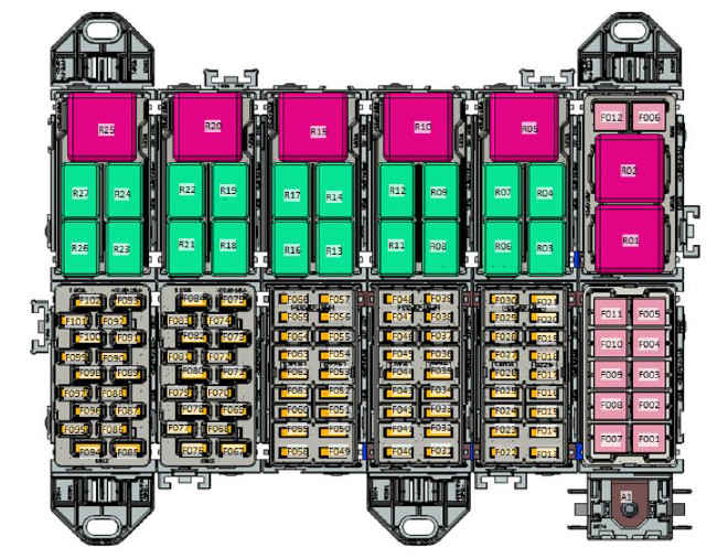
Fuse and Relay Box Diagram View:


2.2.1 Fuses:


2.2.2 Relays:

2.3. Mega Fuse:

This is the fuse with the highest amperage installed for the protection of electrical wiring of vehicles. It is rated at 150 Amperes.

SECTION: 3 ELECTRICAL WIRINGS
3.1.0 Basic Approaches on Fault Finding
We have mentioned in section 2 that the fuses and relays are the first points to be checked in an electrical failure. If there is no failure on fuses or relays, visually inspect the relevant line.
During visual inspection, check for cable sheath damage and whether the conductive part has come out due to friction in wires especially. Connectors on the line may be removed and re-installed again for visual inspection. Check for oxidation, loosening of the pins and check whether they are driven in. If you cannot observe any fault, check for open (disconnection) or short circuit in the line. If the line is also OK, perform measurements of terminal units such as control units.

The main guide in these inspections is the “wiring diagrams.’’ These shall be available in the computer or in the briefcase of each technician as a printed book.
Open circuit or short circuit faults may be “continuous” or may appear intermittently as per conditions. For example, fault may appear when the vehicle falls in a pit or when it enters a turn with a high speed, and it may be non-apparent when the vehicle is on a straight road. Intermittent faults are the most difficult ones to diagnose. In this respect, "passive" faults displayed in the diagnostics unit give us important information. If it is required to repeat the fault condition, one of the methods is making a test drive by connecting a measurement tool and trying to repeat the fault by changing many driving and environmental parameters. For example, if a CAN line disconnection is present between automatic transmission and Engine ECU, it is possible to view the disconnection moment graphically in a road test by connecting an oscilloscope to the transmission CAN line.
Another way of recurring the fault is ‘’static’’ operation. It is checked whether the fault recurs by jiggling the suspected line while the vehicle is parked.
Some examples that may cause a fault in the power line:

3.1.1 Electric Wiring Repair Methods
Padded Add-on Wiring Repair
The electrical wiring may require repairs in case of mechanical damage. In this case, the instructions below shall be followed.
1) Remove the battery negative pole cap. The battery pole caps shall not be removed as the vehicle is operational. Place the removed battery pole cap following reconnecting all cables.
2) Before starting any modification, installation and superstructure operations, the related instructions must be read. The evidence whether the instructions are observed must be kept based on vehicle chassis number. The evidence may be photographs, project schematics etc. or other technical documentation.
3) Replace the whole cable if possible. Extensions in thick cables are very risky and should be avoided. Since it will have a negative effect on the starter current which changes drastically based on ambient temperature, extension of the cable length shall be avoided. Therefore, issues such as late operation or no operation may occur.
4) Padded add-on wiring repair procedure can only be done on cables with cross section larger than 1 mm.
5) Remove the cable sleeve on the wire approximately 25 mm. Remove the insulation on the wire approximately 7-8 mm.
6) Slide the contracted tube appropriate for the cable cross section near the cable with removed insulation around 2-3 mm proximity.
7) Select the extension clip appropriate for the cable cross section. Place the cables with removed insulation on the leads in the extension clip. Ensure that the cable insulation is not inside the terminal.
8-) Select the eyelet of the terminal clamps in align with the cable diameter and additional clip

9) Centre one lead of the extension that will be crimped with the appropriate eyelet of the terminal clamp. Ensure that the terminal lead is tightly fit in the groove on the clamps.
10) Keep the terminal in place so that it will not come out through the cable. Start crimping until the clamp is released (one or two clicks). Do not damage the terminal.
11) Hold the terminal clamp to view the cable diameter indicators. Tighten the clamp until the handles are released, then leave the clamp.
12) Repeat steps 6 to 10 for the non-crimped lead of the cable.
13) Check the attached cable visually.
14) Provide appropriate protection on the repaired section (band etc.).
OK crimping criteria
1-) The terminal should stop in the middle of the two cables. A slight displacement may be acceptable, however one must stick to one of the terminal cables

2) Cable insulation must not enter the terminal in any way.
3) The cables must be visible through the eyelets on the terminal.
APPLICATION OF CONTRACTING TUBE
1-) Slide the contracting tube on the cable extension. Ensure that the tube is centred on the cable extension.
2-) As per the operating instructions for the heat gun; heat the tube starting from the middle and going to the edges and rotate the tube accordingly, until the tube is completely contracted and ensured that it will not contract further. The resin inside the tube must flow out and must be visible from both leads of the tube.
3-) Ensure that the tube is not loose.

NOTE:
1-) The completed extension should be placed at a well-protected area to avoid mechanical damage. It shall not be placed where maximum vibration, distortion, bending and water accumulation occur.
2-) Cables shall not be connected through the leads with removed insulation; the cables shall be repaired as specified above.
3-) Silicon shall not be used for insulation. Contracting tubes shall be used.
4-) Components such as damaged cables and / or connecting parts, sockets, boxes etc. must never be used. If damage has occurred during installation, it must be replaced with new component.
Tube Type add-on Wiring Repair:
The electrical wiring may require repairs in case of mechanical damage. In this case, the instructions below shall be followed.
1) Remove the battery negative pole cap. The battery pole caps shall not be removed as the vehicle is operational. Place the removed battery pole cap following reconnecting all cables.
2) Before starting any modification, installation and superstructure operations, the related instructions must be read. The evidence whether the instructions are observed must be kept based on vehicle chassis number. The evidence may be photographs, project schematics etc. or other technical documentation.
3) Replace the whole cable if possible. Extensions in thick cables are very risky and should be avoided. Since it will have a negative effect on the starter current which changes drastically based on ambient temperature, extension of the cable length shall be avoided. Therefore, issues such as late operation or no operation may occur.
4-) Additional wiring should be provided as Ford Otosan spare parts
5-) Cut off the damaged part of the cable.
6-) Select the extension appropriate for the cable cross section.
7-) It shall be insulated with a tube that contracts with appropriate heat.
8-) Remove the cable sleeve on the wire approximately 25 mm. Remove the insulation on the wire approximately 7-8 mm.

9-) Slide the contracted tube near the cable with removed insulation around 2-3 mm proximity.
10-) The cables with insulation removed shall be inserted until seen through the eyelets of the terminal Ensure that the cable insulation is not inside the terminal.

3.2. Wiring Diagram Abbreviations:


3.3. Electric wiring on vehicle:
There are 21 main wirings on vehicle. You may find detailed information the wirings, connectors on the wirings on the following pages.


14A005 Driver side cab internal wiring 3D View:

14A005 Wiring :
C1A272 Connector

C1E701 / C2CB08 Connectors:

Полный мануал смотри в энциклопедии