
MITSUBISHI FUSO FIGHTER 6M60 Engine Common Rail
(описание)

TABLE OF CONTENTS
1. GENERAL DESCRIPTION
1-1. Outline
2. PRODUCT APPLICATION LIST
2-1. Vehicle Specifications
2-2. Component Part Numbers
3. GENERAL DESCRIPTION OF MAIN NEW FEATURES
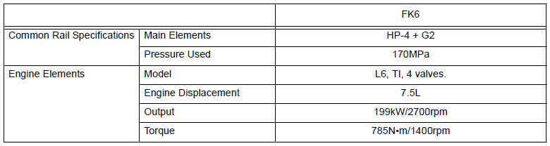
3-1. Common Rail Specifications and Engine Elements
3-2. System Configuration
4. MAIN FUNCTIONAL PARTS
4-1. Changes to the Main Functional Parts
4-2. Supply Pump
4-3. Rail
4-4. Injector
4-5. Sensor Additions and Changes
5. CONTROL OPERATION CHANGES
5-1. Idle-Up
6. ECU RELATED
6-1. External Wiring Diagram
6-2. Terminal Layout
6-3. Terminal Symbol Explanation
7. DIAGNOSTIC TROUBLE CODES (DTC)
7-1. DIAGNOSTIC TROUBLE CODES LIST
GENERAL DESCRIPTION OF MAIN NEW FEATURES
Common Rail Specifications and Engine Elements
System Configuration
Overall System

MAIN FUNCTIONAL PARTS
Changes to the Main Functional Parts
• This section describes only the functional parts that have changed significantly.
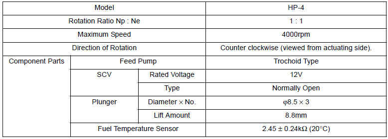
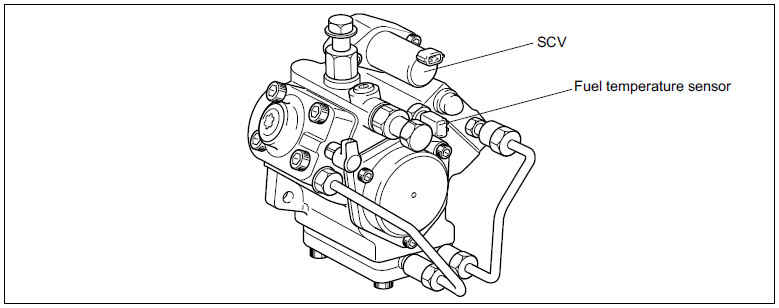
Supply Pump
Changes
Significant changes are listed below.
External View
Construction and Operation
• The ring cam is press fitted into an eccentric position relative to the cam shaft. The ring cam is a triple-lobed cam.
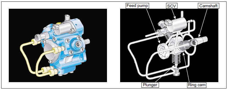
• As the camshaft makes one rotation, the positional relationship between the ring cam and the plunger remains unchanged.
Each plunger makes a single reciprocal movement to pump the fuel. Fuel is drawn in by the feed pump, and the suction quantity is adjusted by the SCV (Suction Control Valve).

Rail
External View

Rail Pressure Sensor
The basic principles and construction are the same as for the conventional model. The pressure detection range has been changed to accommodate the increase in pumping pressure from the supply pump.

Flow Limiter
A flow limiter is employed instead of a flow damper. As with the flow damper, the flow limiter closes the fuel passage to prevent further flow of fuel in the event of an excessive fuel flow. If an abnormal flow occurs, the high pressure forces the piston up. This closes the fuel passage leading to the seat.

Pressure Limiter
The construction and operating principles are the same as for the conventional model. The operating pressure has changed.

Injector
Outline
A compact, energy-saving solenoid-control type TWV (Two-Way Valve) injector has been adopted.
Construction

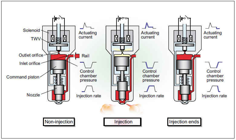
Operation
The TWV (Two-Way Valve) solenoid valve opens and closes the outlet orifice passage to control both the pressure in the control chamber, and the start and end of injection.
a. Non-Injection
When no current is supplied to the solenoid, the TWV (solenoid valve) is pushed downward by the spring, closing the outlet orifice. This equalizes the control chamber pressure forcing the command piston down and the pressure forcing the nozzle needle up. A state of non-injection results because the nozzle needle closes due to the nozzle spring force and the difference in areas to which pressure is being applied.
b. Injection
When current is initially applied to the solenoid, the attraction of the solenoid pulls the TWV (solenoid valve) up, opening the outlet orifice and allowing fuel to flow out of the control chamber. After the fuel flows out, pressure in the control chamber decreases, pulling the command piston up. This causes the nozzle needle to rise and injection to start.
c. End of Injection
When current continues to be applied to the solenoid, the nozzle reaches its maximum lift, where the injection rate is also at the maximum level. When current to the solenoid is turned OFF, the TWV (solenoid valve) falls and closes the orifice.
Fuel then flows into the control chamber via the inlet orifice, increasing pressure and causing the nozzle needle to close immediately and injection to stop.
Sensor Additions and Changes
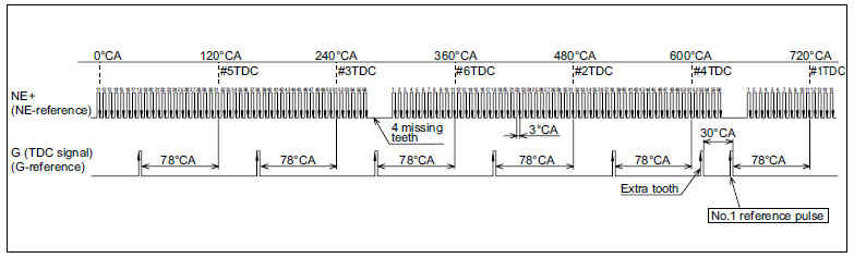
Cylinder Recognition Sensor (TDC Sensor)
• The cylinder recognition sensor is an MRE (Magneto Resistive Element) type. As the teeth in the cylinder recognition sensor pass the sensor, the magnetic resistance in the sensor changes. The change in the voltage generated is converted into a rectangular wave pulse in the IC circuit, and this signal is output to the engine ECU. A cylinder recognition pulsar is installed to the engine camshaft gear, and it outputs the cylinder recognition signal.

• The No. 1 cylinder is located 78°CA from the No. 1 TDC reference signal following the irregular pulse. The interval between each cylinder is the same degree.
Полное описание смотри в