
CASE 788
полная инструкция по ремонту

- TABLE OF CONTENTS
- SPECIFICATIONS
- SCHEMATIC SYMBOLS
- DESCRIPTION OF ELECTRICAL CABINET PRINTED CIRCUIT (STANDARD EQUIPMENT)
- ELECTRICAL CABINET PRINTED CIRCUIT WIRING (STANDARD EQUIPMENT)
- DESCRIPTION OF ELECTRICAL CABINET PRINTED CIRCUIT (OPTIONAL EQUIPMENT)
- ELECTRICAL CABINET PRINTED CIRCUIT WIRING (OPTIONAL EQUIPMENT)
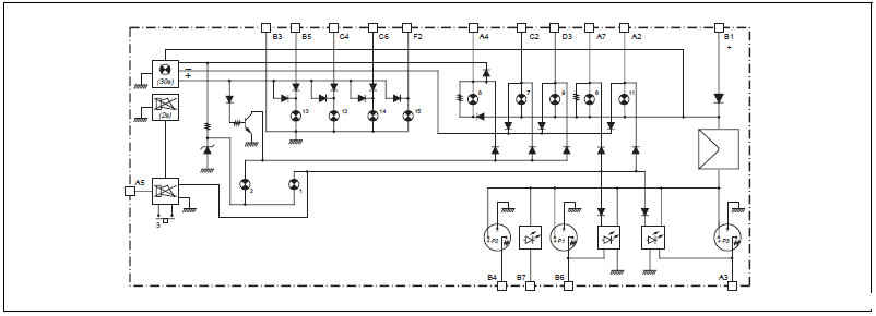
- PRINTED CIRCUIT SCHEMATIC GUIDE
- P10 INSTRUMENT PANEL ELECTRICAL SCHEMATIC (PLATE 1)
- INSTRUMENT PANEL WIRING
- INSTRUMENT PANEL (FRONT FACE)
- RIGHT-HAND CONTROL ARM, LEFT-HAND CONTROL ARM (STANDARD EQUIPMENT)
- RIGHT-HAND AND LEFT-HAND CONTROL ARM WIRING (OPTIONAL EQUIPMENT)
- ELECTRICAL SCHEMATIC (PLATE 2)
- ELECTRICAL SCHEMATIC (PLATE 3)
- ELECTRICAL SCHEMATIC (PLATE 4)
- ELECTRICAL SCHEMATIC (PLATE 5)
- ELECTRICAL SCHEMATIC (PLATE 6)
- ELECTRICAL SCHEMATIC (PLATE 7)
- CAB FLOOR WIRING (STANDARD EQUIPMENT)
- ENGINE MODULE AND UPPERSTRUCTURE WIRING (STANDARD EQUIPMENT)
- ELECTRONIC SYSTEM WIRING
- ELECTRONIC SYSTEM WIRING
- CAB FLOOR WIRING (OPTIONAL EQUIPMENT)
- ENGINE MODULE AND UPPERSTRUCTURE WIRING (OPTIONAL EQUIPMENT)
- CAB AND CAB OPTIONAL EQUIPMENT WIRING
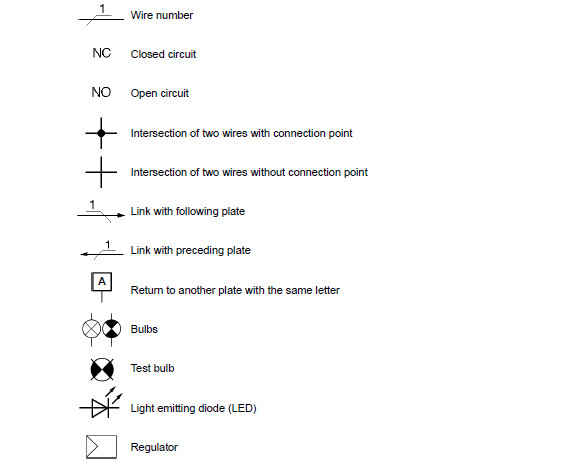
SCHEMATIC SYMBOLS
A (n) Radio/housings
B (n) Indicators/pressure switches/loudspeakers/pressostats/senders/heat sender/gauge
E (n) Lighting components
F (n) Fuses
G (n) Electrical supply generators
H (n) Warning devices (visible and audible)
K (n) Relays
M (n) Motors
P (n) Instruments
R (n) Resistors/heater plugs
S (n) Switches/battery master switch
Sh (n) Shunt resistors
V (n) Diodes
X (n) Supply line connections
Y (n) Solenoid valves, solenoids
NOTE : The (n) shows the component number.
Example : K2 is relay N°2.
The installation position for the harness connector (1) on connector (2) of the printed circuit is identified by a red mark (3) followed by the figure 1 on the printed circuit. This identification corresponds to the position of path 1 of the harness connector (1). This position is completed when the path 1 line is shown by a red ring (4) located on line 1 wire, or by red paint marking.


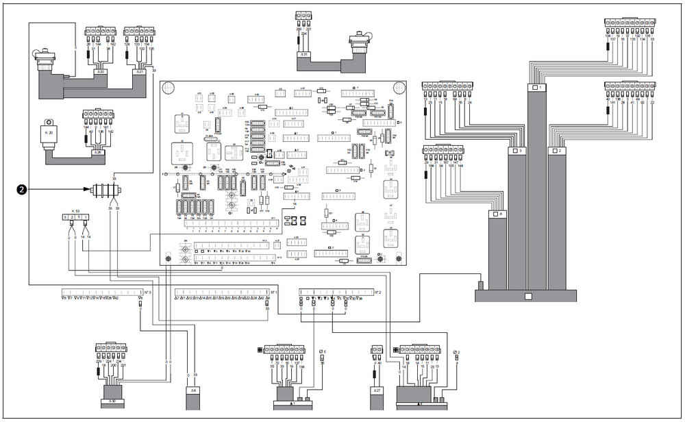
DESCRIPTION OF ELECTRICAL CABINET PRINTED CIRCUIT (STANDARD EQUIPMENT)

1 24 Volts supply before contact
2 12 Volts supply before contact (radio)
3 Not used
F2 5A Fuse, starter switch
F3 7.5A Fuse, instrument panel
F4 5A Fuse, driving position lighting, horn relay
F6 15A Fuse, upperstructure working lights
F7 10A Fuse, horn
F8 15A Fuse, upperstructure power point
F9 10A Fuse, windshield washer, windshield wiper
F10 15A Fuse, ventilation, heater, Fuel heater
F11 7.5A Fuse, cigar lighter
F12 10A Fuse, pilot safety
F15 F16 Not used
F31 15A Fuse, windshield wiper intermittent action
F32 10A Fuse, not used
F33 7.5A Fuse, supply to electronic control box
K1 Starter motor relay
K2 General contact relay
K3 Hourmeter relay
K4 Electrical control box supply relay
K5 Horn relay
K6 Upperstructure and attachment working light relay
K20 Windshield wiper intermittent action
K21 LH control arm pilot safety relay
K53 Fuel heater relay
Sh2, Sh3, Sh4 Shunt
Sh1, Sh5, Sh6, Sh7, Sh8 Not used
V1 General contact diode
Ø 2 Starter connection
Ø 4 Printed circuit earth
Ø 5 Upperstructure power line connection
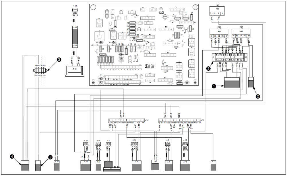
DESCRIPTION OF ELECTRICAL CABINET PRINTED CIRCUIT (OPTIONAL EQUIPMENT)

F1 30A Fuse, cold start assistance (optional)
F5 10A Fuse, working lights and rotary light relay (specific to certain countries)
F13 5A Fuse, overload indicator (optional)
F14 5A Fuse, radio (optional)
F27 5A Fuse, adjustable or articulated boom (optional)
F30 15A Fuse, cab working lights (optional)
K15 Cold start assistance relay (optional)
K50 Adjustable boom raising height limiter relay (optional)
K51 Adjustable boom lowering range limitation relay
K53 Fuel heater relay
R10 0.85 ohm Resistor
V4 Radio LED (optional)
V21 Overload indicator lamp (optional)
V22 Rotary light indicator lamp (specific to certain countries)
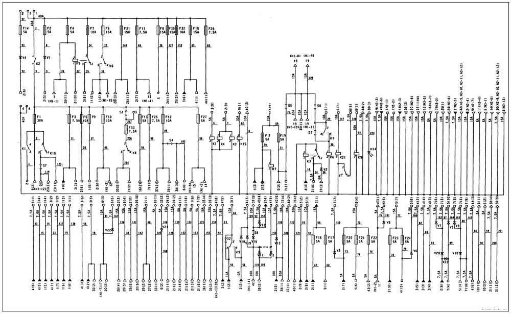
PRINTED CIRCUIT SCHEMATIC GUIDE
1 24 volts supply before contact
2 12 volts supply before contact radio
3 Electronic control box 24 volt supply and troubleshooting test socket
F1 30A Fuse, cold start assistance (optional)
F2 5A Fuse, starter switch
F3 7.5A Fuse, instrument panel
F4 5A Fuse, cab lighting, horn relay
F5 10A Fuse, working lights and rotary light relay (specific to certain countries)
F6 15A Fuse, uperstructure working lights
F7 10A Fuse, horn
F8 15A Fuse, upperstructure power point
F9 10A Fuse, windshield wiper, windshield washer
F10 15A Fuse, ventilation, heater, fuel oil heating
F11 7.5A Fuse, cigarette lighter
F12 10A Fuse, pilot safety
F13 5 A Fuse, overload indicator (optional)
F14 5A Fuse, radio (optional)
F15 Not used
F16 Not used
F17 Not used
F18 Not used
F19 Not used
F20 Not used
F21 Not used
F22 Not used
F23 Not used
F24 Not used
F25 Not used
F26 Not used
F27 5A Fuse, adjustable and articulated boom (optional)
F30 15A Fuse, cab working lights (optional)
F31 15A Fuse, Windshield wiper intermittent action
F32 10A Fuse, Not used
F33 7.5A Fuse, electronic control box
H14 Diagnostic LED
K1 Starter motor
K2 24V, 50A General contact relay
K3 Hourmeter relay
K4 Electrical control box supply relay
K5 Horn relay
K6 Working light relay
K7 Not used
K9 Not used
K10 Not used
K15 Cold start assistance relay (optional)
K20 Windshield wiper intermittent action
K21 Left-hand control arm pilot safety relay
K52 Not used
Sh2 Shunt
Sh3 Shunt
Sh4 Shunt
Sh6 Shunt
Sh1, Sh5, Sh7, Sh8 Not used
V1 General contact diode
V2 Diode, Not used
V3 Not used
V4 Radio diode (optional)
V5 Diode, Not used
V6 Diode, Not used
V7 Diode, Not used
V8 Diode, Not used
V9 Diode, Not used
V10 Diode, Not used
V11 Diode, Not used
V16, V17, V18, V19 Diode, Not used
V20 Diode, Not used
V21 Overload indicator diode (optional)
V22 Rotary light diode (specific to certain countries)
V23Diode, Not used
Ø 2 Starter connection
Ø 4 Printed circuit earth
Ø 5 Upperstructure power line connection
P10 INSTRUMENT PANEL ELECTRICAL SCHEMATIC (PLATE 1)
A2 Minimum pilot pressure red warning lamp connector
A3 Hydraulic oil temperature indicator connector
A4 Battery charge red warning lamp connector
A5 Audible warning red, orange indicator lamp connector
A7 Engine oil pressure red warning lamp connector
B1 24 Volt supply
B3 Earth
B4 Fuel level indicator connector
B5 Gauge lighting connector
B6 Engine coolant temperature indicator connector
B7 Fuel minimum level connector
C2 Air filter restriction red warning lamp connector
C4 Overload indicator orange warning lamp connector (optional)
C6 Connector Not used
D3 Hydraulic oil filter restriction red warning lamp connector
F2 Rotary light orange indicator lamp connector (optional)
P1 Engine coolant temperature indicator
P2 Fuel level gauge
P3 Hydraulic oil temperature indicator
1 Stop alarm red warning lamp
2 Alarm orange warning lamp
3 Audible warning stop push button
6 Engine oil pressure red warning lamp
7 Air filter restriction red warning lamp
8 Battery charge red warning lamp
9 Hydraulic oil filters restriction red warning lamp
11 Minimum pilot pressure red warning lamp
12 Overload indicator orange warning lamp (optional)
13 Indicator lighting lamp
14 Not used
15 Rotary light orange indicator lamp (optional)
INSTRUMENT PANEL WIRING
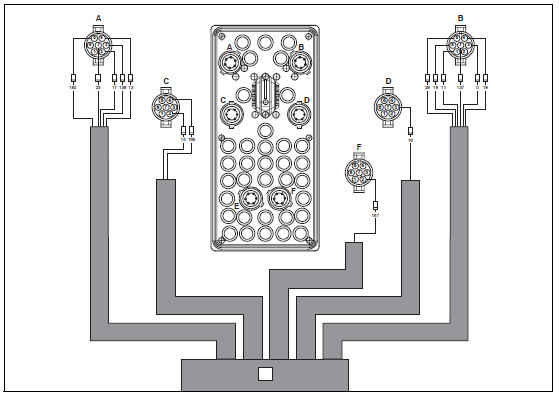
A 7-way connector : minimum pilot pressure red warning lamp, hydraulic oil temperature indicator, battery charge red warning lamp, audible warning cut-out push button, engine oil pressure red warning lamp, alarm orange warning lamp, stop alarm red warning lamp.
B 7-way connector : 24 Volt supply, earth, fuel level gauge, indicator lighting, engine coolant temperature indicator.
C 7-way connector : air filter restriction red warning lamp, overload indicator orange warning lamp (optional).
D 7-way connector : hydraulic oil filter restriction red warning lamp.
F 7-way connector : rotary light orange indicator lamp (optional).
Полный мануал в