
CROWN RR 5200 DC
(схемы, ремонт, диагностика)
Introduction to Diagram Usage
Schematic
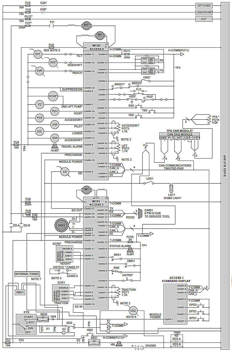
• Power up diagram. Illustrates the circuitry involved in getting the truck system to an operating mode (Can Interface, Access 1,2,3, Controller, Contactor, ect.).
• Circuitry which stands alone and is separate from truck operation is shown in block form with the pictorials detailing the circuitry (e.g. light package, displays, wire guidance, freezer condition).
Pictorials
• Terminal board and connector numbering on the pictorials are in two classes; power unit and platform.
Power unit TB's and CA's are even 100's (200, 400, 600 etc.) and platform TB's and CA's are odd 100's (100, 300, 500 etc.). On manup trucks
(SP, TS, TSP etc.), odd and even 100's will be present on the wiring diagrams. Man-down trucks, which don't have a platform (stand-up rider, pallet etc.), only even 100's will be present.
• Wiring starts at a central location (e.g. distribution board) and wiring connection points are numbered with the lowest number odd or even. The next wiring connection point from the distribution board are then numbered with the next group of 100's and so on for each connection point removed from the central location.
• Terminal board and connector numbering is sequential on each consecutive page. In this way a wiring address giving a connector number or terminal board number will indicate which direction to look in the diagrams for the other end of the wire.
When wiring goes to a component and not a terminal board or connector, a reference terminal board is used and is shown with a dashed line box with the reference terminal board number in parenthesis.
This terminal board will not appear on the truck and only present as a wiring directory.
• Input/Output arrows may appear at terminal boards and connectors. These indicate whether what the wire is carrying is incoming or outgoing.
This is helpful when tracing the origin of the signal or voltage.
• The truck has been sectioned with one page covering each section. When options affect the wiring in a section, an additional page is added which duplicates wiring that is identical and adds the option wiring. In this way only one page of the truck section is required for the applicable truck configuration.
• Wiring that is identified by color rather than number will typically be a cable or wires with vendor componentry.
• Page titles, listed at the beginning of the electrical diagrams, indicate the subsystem or section of truck wiring that is covered by each page.
Полный мануал смотри в